 |
 It’s time for a change

Mike Weir, VE9KK, is a regular contributor to AmateurRadio.com and writes from New Brunswick, Canada. Contact him at [email protected].
Ham College episode 1 coming this weekend
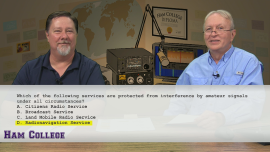
The first official episode of AmateurLogic’s Ham College will be shot this Friday evening, January 30th at 7:00 CST, 0100 UTC.
You can watch us produce it live and participate in the chatroom at www.live.amateurlogic.tv.
This is a new show for those wanting to join the hobby and new Hams as well.
George Thomas, W5JDX, is co-host of AmateurLogic.TV, an original amateur radio video program hosted by George Thomas (W5JDX), Tommy Martin (N5ZNO), Peter Berrett (VK3PB), and Emile Diodene (KE5QKR). Contact him at [email protected].
Poppet 160m AM transceiver
This little top band AM transmitter and a companion receiver were first published in the GQRP club SPRAT magazine. This TX version was built by M0DAD. Where the noise floor allows, 160m AM is quite popular for local nets. There is something nice about “rolling your own” builds and getting satisfying results without spending a fortune. For daytime local use 160m AM is a great mode and rigs are simple. I am still surprised that more is not made of AM on 10m at night for local nets here in the UK.
See http://www.delboyonline.co.uk/m0dad/construcion/poppet_top_band_am_transmitter.htm.
Roger Lapthorn, G3XBM, is a regular contributor to AmateurRadio.com and writes from Cambridge, England.
CLE190 Logs
 |
| YJ-200KHz - Victoria Int'l |
 |
| CFL Crud |
25 04:00 198 DIW Dixon, NC, USA
24 06:00 200 YJ Victoria - Sidney Island, BC, CAN
24 04:00 200 YDL Dease Lake, BC, CAN
25 07:00 200 UAB Anahim Lake, BC, CAN
24 04:00 201 ZWN Winnipeg, MB, CAN
24 12:00 201 IP Lufthansa, AZ, USA
24 07:00 201 GV Greenville, TX, USA
26 05:40 201 YVZ Deer Lake, ON, CA
24 06:00 203 ZKI Kitimat, BC, CAN
24 06:00 203 YBL Campbell River, BC, CAN
24 06:00 203 TCY Tracy Municipal Apt, CA, USA
24 04:00 204 ZQR Regina, SK, CAN
24 11:00 205 XZ Wawa, ON, CAN
24 04:00 205 COR Corcoran, CA, USA
24 04:00 206 SOW Show Low Regional Apt, AZ, USA
24 04:00 206 EF Castlegar, BC, CAN
24 04:00 207 YNE Norway House, MB, CAN
24 04:00 207 PY Fort Chipewyan, AB, CAN
24 07:00 209 ITR Burlington, CO, USA
24 04:00 209 IB Atikokan, ON, CAN
25 14:00 209 HGT Tusi AHP, CA, USA
24 04:00 209 CYT Yakataga Apt, ALS
24 04:00 211 HDG Gooding, ID, USA
24 04:00 212 YGX Gillam, MB, CAN
25 04:00 212 MPZ Mount Pleasant, IA, USA
24 04:00 212 CGL Juneau, ALS
24 07:00 212 CFV Coffeyville, KS, USA
24 04:00 214 LU Abbotsford, BC, CAN
24 04:00 215 ZAB Edmonton (Intl Apt), AB, CAN
24 11:00 215 TQH Tahlequah, OK, USA
24 04:00 216 GRF Fort Lewis, WA, USA
24 04:00 216 CLB Wilmington, NC, USA
24 04:00 217 EC Enoch, UT, USA
24 11:00 218 RL Red Lake, ON, CAN
24 04:00 218 PR Prince Rupert, BC, CAN
24 04:00 219 ZRS Regina, SK, CAN
24 07:00 220 HLE Hailey, ID, USA
24 04:00 221 QU Grande Prairie, AB, CAN
24 04:00 222 WY Wrigley, NT, CAN
24 04:00 223 YKA Kamloops, BC, CAN
24 04:00 223 AFE Kake Apt, ALS
25 11:00 224 MO Moosonee, ON, CAN
24 04:00 224 DN Dauphin, MB, CAN
25 04:00 225 X5 Vegreville, AB, CAN
24 04:00 225 LWG Lewisburg - Corvallis, OR, USA
25 04:00 227 YAC Cat Lake, ON, CAN
25 12:00 227 MHM Minchumina, ALS
24 04:00 227 CG Castlegar, BC, CAN
24 04:00 229 AKW Klawock, ALS
24 06:00 230 YD Smithers, BC, CAN
24 07:00 230 VG Vermilion, AB, CAN
24 11:00 230 NRN Norton, KS, USA
24 07:00 230 BI Bismarck, ND, USA
24 07:00 233 QN Nakina, ON, CAN
24 07:00 233 OKS Oshkosh, NE, USA
25 14:00 233 LG Seal Beach, CA, USA
24 04:00 233 BWP Breckenridge, ND, USA
24 04:00 233 BR Brandon, MB, CAN
25 12:00 233 AZN Amazon, MO, USA
24 04:00 233 ALJ Hinchinbrook Island, ALS
25 04:00 235 CN Cochrane, ON, CAN
25 04:00 236 ZRJ Round Lake, ON, CAN
24 04:00 236 YZA Ashcroft, BC, CAN
24 04:00 236 FOR Forsyth, MT, USA
24 04:00 238 MPA Nampa, ID, USA
24 04:00 239 OJ High Level, AB, CAN
25 04:00 381.5 SJX St James, MI, USA
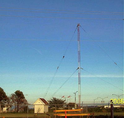
Listening for NDBs is a practical way to check out your LF receive capability, should you be interested in developing a good 630m station or in following the nuances of night-to-night MF propagation.
Steve McDonald, VE7SL, is a regular contributor to AmateurRadio.com and writes from British Columbia, Canada. Contact him at [email protected].
January Phase Noise
Radio activity around here was asymptotically approaching zero until this past weekend when I managed to put about two hours into the ARRL January VHF contest. In brief, here’s what’s happening around K8GU:
- 47Q x 17G on 6 (8/2), 2 (29/11), and 432 (10/4) in ARRL January VHF. The 6-meter QSOs were all made with an HF antenna. I ran 100 watts on 432 so I’m ineligible for the 3-band category. Heard, but didn’t work, N1GC (EM59), K1TEO (FN31, whom I almost always work), and VE3??? (FN03, I had the whole call at the time but forgot, working K1RZ).
- I did not work EP6T on any bands and really don’t care. I didn’t hear much of the jamming when I did listen (on 40 and 80). To paraphrase KE9V quoting JA1NUT, “I’m kind of over DXing.” Who has time for this, anyway?
- Speaking of the seedy underbelly of DXing…do you know what a “QSL grubber” is? I’ve experienced a couple of different variations on this in the past year and it’s disturbing. One guy was asking about specific QSOs and provided detailed description of (my) signal characteristics. Nevermind the fact that I never operated on the band he mentioned during that operation. He sent similar e-mail to several friends. As if DX operators don’t talk to each other? The DXCC desk has been notified. I wonder if anybody actually falls for it or gives in, though?
- I made token efforts in NAQP CW and Phone to chalk up a participation multiplier for PVRC in the three-way PVRC-SMC-NCCC competition.
- No homebrewing or repair work has been undertaken since the summer.
- The baby can crawl and wants to walk so badly she can’t stand it. The end is near.
- I took Evan to the Odenton Hamfest on Sunday morning. The highlight for him was stopping for donuts…and stopping at a playground on the way home. Bought some Snap-N-Seal F-type compression connectors for a work project, part of my quest to find the perfect F-connector for the perfect RG-6 type cable (quad-shielded, flooded). More on this in a future post.
- It seems there are plenty of Elecraft K2’s on the market these days. As the price slips below 1000 USD for a loaded K2/100, this radio is becoming a good buy. As a secondary note, they all seem to be “professionally constructed by a well-known builder.” This leads me to wonder what fraction of K2s were built by someone other than the owner (I estimated this fraction once to be about 1/3 of them). I also wonder if people who built their own K2s hold onto them longer?
And so it goes, time to punch my card…
Ethan Miller, K8GU, is a regular contributor to AmateurRadio.com and writes from Maryland, USA. Contact him at [email protected].
First garden portable activity of the year on SO-50
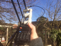
Yesterday, it was a cold but dry day and I thought it would be fun to go out in the garden and see what I could hear and work on SO-50. I quickly put a bit of charge into the UV-5R portable and assembled the Elk yagi.
The first pass I tried was off to the east and although I could hear plenty, I didn’t manage a QSO. The next pass after that was pretty much overhead and I was a lot more successful, working 2E1EBX also using handheld gear, over on the Norfolk coast and then Yuri, UT1FG/MM in IO90 on his way up to Hull.
Really enjoyable and not too cold.
Tim Kirby, G4VXE, is a regular contributor to AmateurRadio.com and writes from Oxfordshire, England. Contact him at [email protected].
First garden portable activity of the year on SO-50
Yesterday, it was a cold but dry day and I thought it would be fun to go out in the garden and see what I could hear and work on SO-50. I quickly put a bit of charge into the UV-5R portable and assembled the Elk yagi.
The first pass I tried was off to the east and although I could hear plenty, I didn’t manage a QSO. The next pass after that was pretty much overhead and I was a lot more successful, working 2E1EBX also using handheld gear, over on the Norfolk coast and then Yuri, UT1FG/MM in IO90 on his way up to Hull.
Really enjoyable and not too cold.
Tim Kirby, G4VXE, is a regular contributor to AmateurRadio.com and writes from Oxfordshire, England. Contact him at [email protected].
 Ham Radio Deluxe |
 W5SWL Electronics |
 Ham Radio Prep |
 KB3IFH QSL Cards  Hip Ham Shirts  HamRadioAuctions HamRadioAuctions Reliance Antennas Reliance Antennas Enigma Shop Enigma Shop |  morseDX  Ni4L Antennas  R&L Electronics R&L Electronics antennas.us antennas.us QRV QRV |
- Matt W1MST, Managing Editor
