 |
 Even lower cost Pixie kits!
Steve, G1KQH has pointed me to a link with 40m Pixie kits at incredible prices. At these prices there is no way the parts could be bought for less than the kit. The version I bought for $10 looks identical. All you need is a morse key, battery 40m antenna and walkman type headphones and you have a credible 40m CW transceiver. It really works.
Yoohoo Roger,
Now I back in front of the Pixie bargain game hunt, after finding the the best price!!!
http://www.banggood.com/DIY-Radio-40M-CW-Shortwave-Transmitter-Kit-Receiver-7_023-7_026MHz-p-973111.html
£2.89!!!!!!!
and if you buy more than 2 it gets cheaper!!
Not forgetting this includes free shipping. Unbelievable.
Roger Lapthorn, G3XBM, is a regular contributor to AmateurRadio.com and writes from Cambridge, England.
AmateurLogic Live Friday, April 10th
We will be shooting the next episode of AmateurLogic live this Friday night at 7:00 PM CDT, 000 UTC. Join us at www.live.amateurlogic.tv for the uncut version.
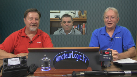
George Thomas, W5JDX, is co-host of AmateurLogic.TV, an original amateur radio video program hosted by George Thomas (W5JDX), Tommy Martin (N5ZNO), Peter Berrett (VK3PB), and Emile Diodene (KE5QKR). Contact him at [email protected].
The Pixie money game!
Well the story continues!! I have now found the Pixie kits cheaper yet again!!! The complete kit as above (inc PCB components and Xtal), all for a penny pinching £2.89p ($4.30 US), and the more you buy the cheaper it gets! Oh yes I forgot the price "Includes" shipping!!
You could buy several kits without busting the bank, and put them on different Bands with Xtal and small mod of low pass filter changes.
Is this now the cheapest Transceiver kit in the world, or can anyone find them cheaper still??
Steve, G1KQH, is a regular contributor to AmateurRadio.com and writes from England. Contact him at [email protected].
Car upgrade to LEDs
It was time to upgrade the interior lights in my 2004 Volvo. I got some lamps from Ebay specified as 42 mm LED Festoon, 80-85 lm, 12V. As many others have experienced also, they kept on glowing faintly after the door was closed. But when the ignition was turned off the lamps were completely off also, so there was no danger of draining the battery. Still this is not the way one expects lamps to behave.
One can get more expensive LED lamps which avoid this faint glow, “Canbus error free” seems to be the way to specify this. But mine were of the plain type, and the problem seems to be the leakage current in the FET switches that turn the lights on and off. It is tiny, but enough to give a voltage large enough to turn the LEDs on. An additional resistor load will lower the voltage below that threshold.
This requires a parallel resistor. Some have used 1k, others larger values. I did some trials and found that 10k worked well, while 22k didn’t completely eliminate the faint glow. The advantage is that 10k will only dissipate 18 mW @13.5 Volts, while the 1k will dissipate ten times that. Therefore I could use a small 1/4 W type. I soldered it on the back of the LED-board as the image shows.

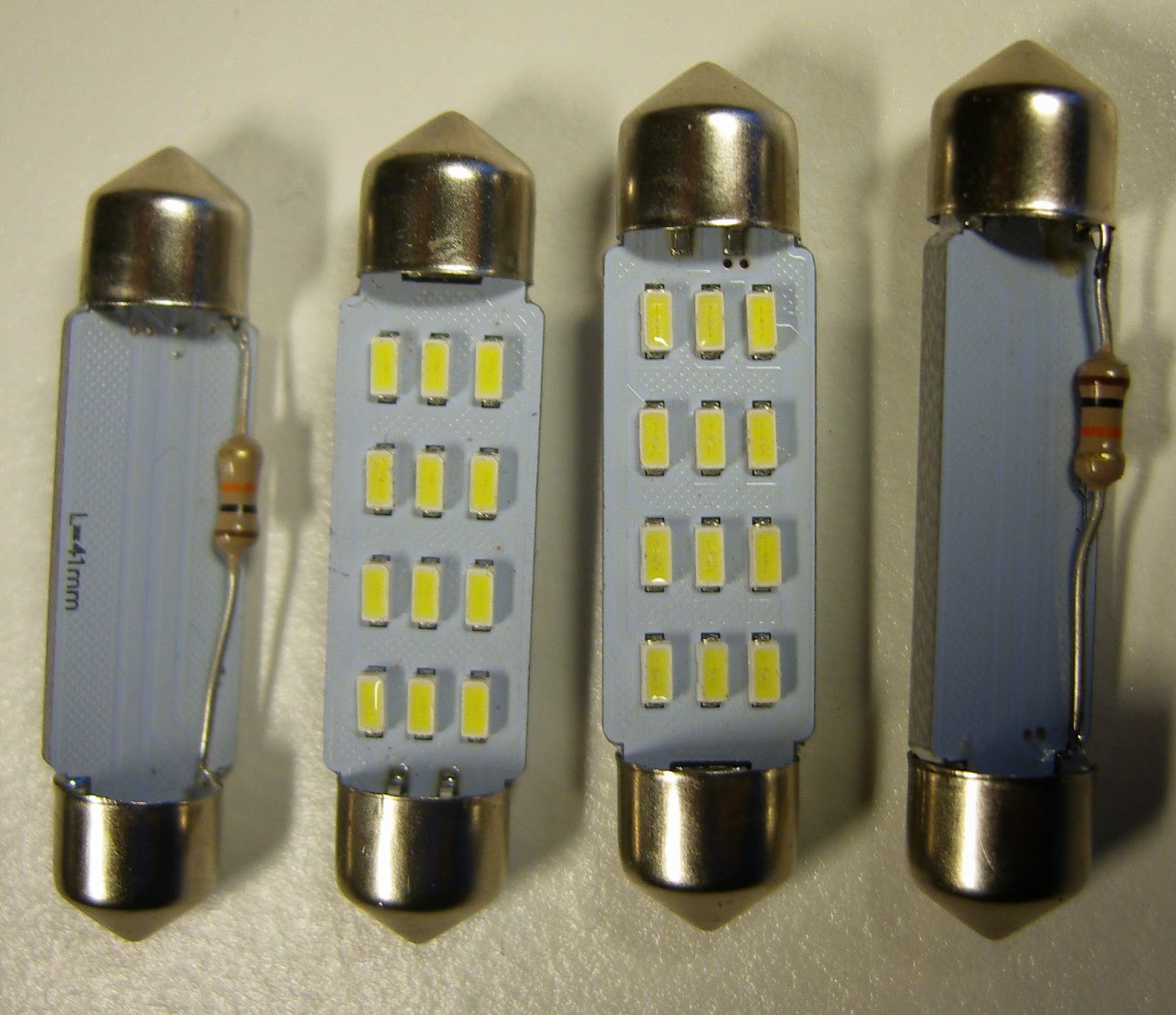
The reason for switching to LED is not really to save energy as the savings aren’t that great anyway. The whiter and brighter light is more important as you can see in the image with the LED to the left and the old incandescent lamp to the right.
While at it, I just had to do some reverse engineering of the LED lamps. There seems to be four parallel groups of three series-connected LEDs (the three in a row) giving a forward voltage of about 8.3 V. They are driven via a resistor of 120 ohms in series with what seems to be a bridge rectifier since the lamps don’t depend on being connected in a particular way with respect to polarity.
In total it draws 18 mA @ 12V and 28 mA @ 13.5 V, i.e. 0.3-0.4 W, compared to 10 W for the bulb it replaced. This is not a very sophisticated way of constructing a LED lamp as there is no constant current regulation. The intensity will therefore vary with voltage, but hopefully it will work well here.
Sverre Holm, LA3ZA, is a regular contributor to AmateurRadio.com and writes from Norway. Contact him at [email protected].
Car upgrade to LEDs
It was time to upgrade the interior lights in my 2004 Volvo. I got some lamps from Ebay specified as LED Festoon, 80-85lm, 12V. As many others have experienced they kept on glowing faintly after the door was closed. When the ignition was turned off the lamps were completely off also, so there was no danger of draining the battery. Still it is not the way one expects lamps to behave.
One can get more expensive LED lamps which avoid this faint glow, “Canbus error free” seems to be the way to specify this. But mine were of the plain type, and the problem seems to be the leakage current in the FET switches that turn the lights on and off.
All it takes to solve it is a parallel resistor. Some have used 1k, others larger values. I just made some trials and found that 10k worked well. The advantage is that 10k will only dissipate 18 mW @13.5 Volts, while the 1k will dissipate ten times that, so I could use a small 1/4 W type. I soldered it on the back of the board as the image shows.
The reason for switching to LED is not really to save energy as the savings aren’t that great anyway. The whiter and brighter light is more important as you can see in the image with the LED to the left and the old incandescent lamp to the right.
While at it, I just had to do some reverse engineering of the LED lamps. There seems to be four parallel groups of three series-connected LEDs (the three in a row) giving a forward voltage of about 8.3 V. They are driven via a resistor of 120 ohms in series with what seems to be a bridge rectifier since the lamps don’t depend on being connected in a particular way with respect to polarity. They draw 18 mA @ 12V and 28 mA @ 13.5 V. This is not a very fancy way of constructing a LED lamp as there is no constant current regulation. The intensity will therefore vary with voltage, but hopefully it will work well here.
Sverre Holm, LA3ZA, is a regular contributor to AmateurRadio.com and writes from Norway. Contact him at [email protected].
Doing surgery on the Elecraft K3 part 1
 |
| It's time for some surgery. |
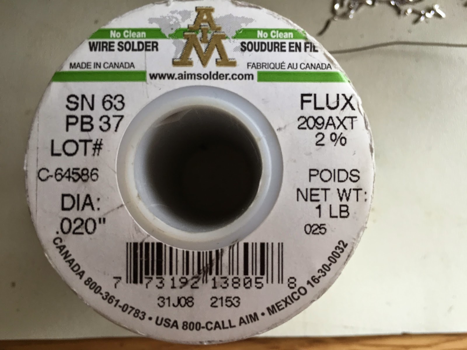
First off an anti static mat with a wrist strap, when dealing with state of the art radios this is a must! A medium quality soldering station makes your soldering jobs a pleasure. I have the WellerWES51, this is a nice temperature controled unit. The tips can be changed out for varied soldering jobs and what's nice with this grade of soldering stations the tips heat up very fast and stay hot.


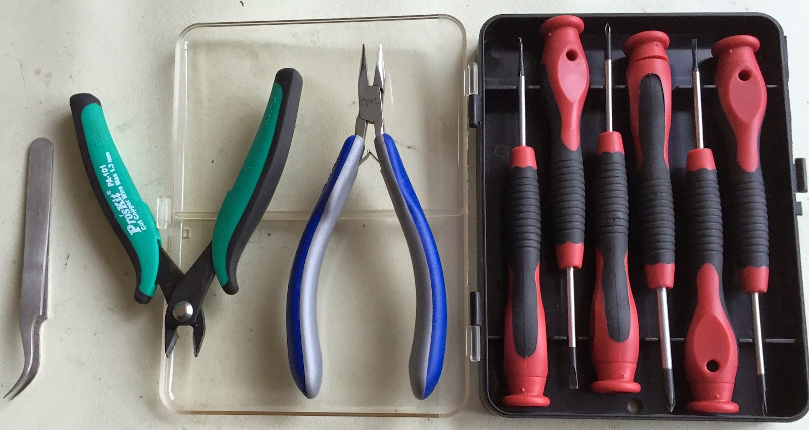 rolling off the desk. When you solder there is smoke and it's a good idea to pickup a fume fan of some type. I purchased the Fume trap brand of fans. It works great and keeps the fumes away from you breathing them in. You then have the hand tools that again have to be chosen and purchased wisely. You don't have to break the bank but don't go for super cheap. For this job I will be using my screw drivers, tweezers and diagonal cutters. Finally with this project I have to remove old solder from the pads that are on the K3's PC board. This is a part of the project if things go bad they can go really bad! In the past I have used the hand held spring loaded desoldering pump. They are ok but not great, I took the plunge and purchased the Hakko 808 desoldering tool. This has been one my best investments! This are most of the tools that I am going to be using and for this post that's about all I'm going to talk about. My next post (part 2) I am going to get into the steps I used to change P30 and P35 headers.
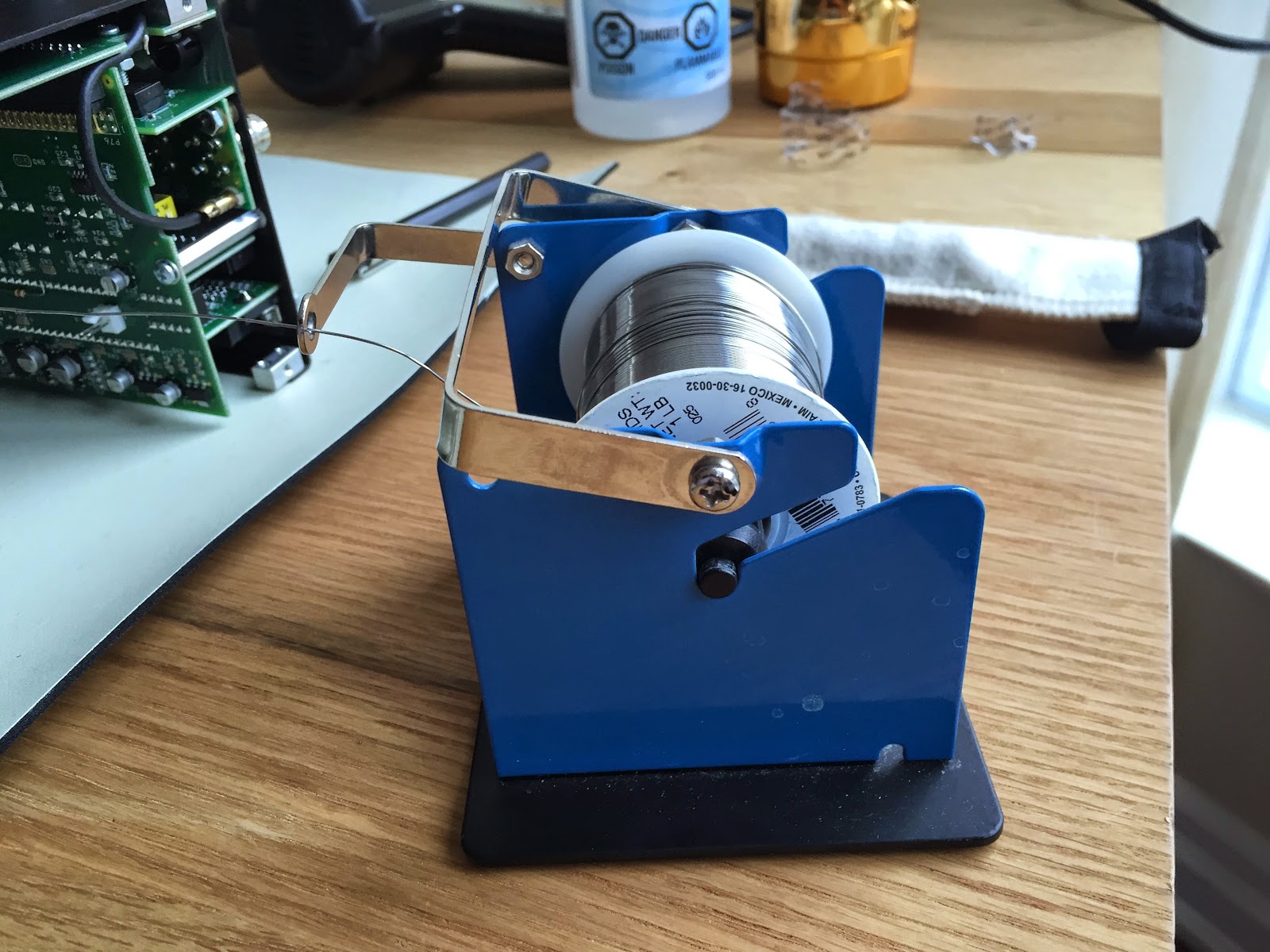
Mike Weir, VE9KK, is a regular contributor to AmateurRadio.com and writes from New Brunswick, Canada. Contact him at [email protected].
New Band For ZS Hams
 Sharp-eyed Roger, G3XBM, has brought attention to the recent news of a new amateur allocation granted to South Africa's amateur radio community! It's just a small slice of a band but in an exceptionally interesting part of the spectrum ... 40MHz!
 Amateurs have been given 'propagation studies' permission to transmit between 40.675MHz and 40.685MHz as 'primary users' and use up to 26dBW (400Watts) of power ... a healthy assignment.
I'm not sure where the push for this new band has risen from but no doubt from within the amateur radio community of South Africa ... and kudos to the SA radio authority for establishing this unique amateur band.
Myself and others, have often stated that an amateur allocation in the 40MHz region would be a wonderful part of the spectrum in which to experiment. Almost midway between the two "magic bands" (10m and 6m), the propagation opportunities of 40MHz would be most unique and abundant.
With Solar Cycle 24 being such a weak cycle, most of North America and particularly the western half, saw almost no F2 openings of any significance. Absent were the all-day long bone-crushing signals from the east coast, followed by the spotlight propagation-sweep down to South and Central America and finally over to Japan for another few hours of ear-shattering JA signals ... none of this for Cycle 24. Yet, in spite of the lower MUF's, I noted dozens and dozens of days when the F2 MUF would shoot up to the high 43MHz region and hang in for hours and hours ... just as it did on 6m in previous cycles.
Having even a small slice of spectrum at 40MHz would give amateurs a golden opportunity to follow some exceptionally interesting propagation trends during the next few cycles ... all predicted to be stinkers, some saying even worse than '24'. With 40MHz supporting the F2, Es, TEP and Auroral modes, there would be much exciting propagation to support activity in this region.
Maybe it's time North American amateur's start talking about a new slice of the 40MHz pie ... surely there is enough space to share.
Steve McDonald, VE7SL, is a regular contributor to AmateurRadio.com and writes from British Columbia, Canada. Contact him at [email protected].
 Ham Radio Deluxe |
 W5SWL Electronics |
 Ham Radio Prep |
 KB3IFH QSL Cards  Hip Ham Shirts  HamRadioAuctions HamRadioAuctions Reliance Antennas Reliance Antennas Enigma Shop Enigma Shop |  morseDX  Ni4L Antennas  R&L Electronics R&L Electronics antennas.us antennas.us QRV QRV |
- Matt W1MST, Managing Editor
