 |
 Magnetic Loops on HF
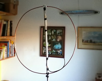 |
| 10m band loop |
A magnetic loop can be a very effective HF antenna, especially when the very sharp tuning is not an issue. They can be very efficient but there is a trade between bandwidth and efficiency. They are ideal for modes that do not need frequent retuning such as PSK31, JT65 or WSPR. Ideally the inductor should be made of copper pipe or thick coax and the capacitors need to be low loss and high voltage types. Tuning is usually very sharp. Having said all this. quite decent results have been obtained with loops made of quite thin wire.
See https://sites.google.com/site/g3xbmqrp3/antennas/magloop .
Roger Lapthorn, G3XBM, is a regular contributor to AmateurRadio.com and writes from Cambridge, England.
E-field probes
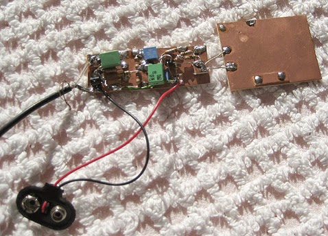
A very successful antenna for VLF, LF and MF receive only is an E-field probe. Ideally these should be mounted outside the house with some experiments to find the quietest spot. Size is not important and these are much smaller than many antennas for much higher frequencies. The picture shows an example EFP. This is the complete antenna – no wires or loops etc are needed in addition. They can be made by just about anyone, so there is nothing stopping you having fun on 136,472 or even VLF RX. Some people have built these inside a short length of uPVC pipe. The important thing is they are very small and work well on the lower bands.
I have also used EFPs as mag mounts on the car when looking for my signal on 136kHz QRSS3. These are very compact antennas. PA0RDT has created a good design that many people are using.
See https://sites.google.com/site/g3xbmqrp3/antennas/efp .
Roger Lapthorn, G3XBM, is a regular contributor to AmateurRadio.com and writes from Cambridge, England.
Elecraft K3S
I see Elecraft has launched a deluxe version of its K3 transceiver. The K3 was already a pretty good rig and the S version will be even better, but sadly far too expensive. I guess Elecraft is right that this will be many times less expensive than similarly spec’d transceivers, but to me this is still far too much for an amateur radio rig. Don’t forget that lots of the features cost more – like the mic and 2m!
At half the price maybe, but certainly out of the question here in the UK when shipping, import duty and VAT have to be added. I am able to get lots of fun from our hobby spending just a small fraction of the cost. There will always be people who will pay these prices and buy a tower and a big beam. Sorry, but this is not for me. I wish Elecraft well but feel they will need to slash prices soon to compete with the Chinese. An alternative is for Elecraft kits to be shipped from China. Sorry, but this may be the only way they will be able to compete in the future.
Roger Lapthorn, G3XBM, is a regular contributor to AmateurRadio.com and writes from Cambridge, England.
The scoop from Elecraft at FDIM
The new product is an enhanced K3 with many new features - here's a link to a .pdf which explains them all in detail. And here's a link to a FAQ.
It appears the new K3S will be approximately $500 more than the old version, and the original K3 has been "discontinued" or "replaced" - whichever you prefer. In addition, it appears most, but not all the enhancements will be retro-fittable to make a K3 a K3S. The new bezel and the attenuator, for instance, will not.

I wonder - how does the guy feel who took delivery on a brandy new K3, in the very recent past? Are they happy because they squeaked under the wire and got their K3 at the lower price? Or are they feeling a bit miffed because they ordered and received something that is no longer "the latest and the greatest"? Except for the cosmetics, it appears that you can pretty much turn your existing K3 almost into a K3S - and you do have a "system" that is continually upgradable. So if you're an Elecraft owner, you can take comfort in the fact that when you buy something, the company does its best to stand behind their product and you.
I for one, am quite happy with my KX3's. They're all the radio I need, and should Elecraft come out with a KX3S tomorrow, I would not be bothered in the least.
The morning UStream feed from FDIM was disappointing. If you attempted to watch it, you saw that only a portion of the video picture appeared and none of the audio. Basically, you missed the entire Elecraft K3S presentation. Things got straightened out during Rev. Dobb's presentation and we were able to hear that the good Reverend was inaugurated as QRP-ARCI's very first Lifetime Member.
The silver lining is that hopefully the feed will be up and running normally for the remaining sessions.
72 de Larry W2LJ
QRP - When you care to send the very least!
Larry Makoski, W2LJ, is a regular contributor to AmateurRadio.com and writes from New Jersey, USA. Contact him at [email protected].
Are You Going To Dayton?
This is a question I ask of vendors I order equipment and amateur radio goodies from. You should ask the same of your vendors. If your vendors don’t support Dayton, perhaps you should consider supporting different vendors. Why, you ask? Dayton is the largest amateur radio event in the US and perhaps the western hemisphere. It’s struggled over the years. However, the visual appearance and condition of Hara Arena tends to tarnish the state of the Dayton Hamvention, in my opinion. I think the Hamvention is actually doing well. Attendance was up last year. Looking at the schedule of seminars this morning, it’s a wonderful collection of varied topics, with something for everyone. The flea market is huge and it’s exhausting to cover the entire area in the three days. If your vendor is devoted to amateur radio, they should come to the Dayton Hamvention. If they can’t make a profit attending and selling products or generating sales leads, perhaps something is wrong with their products, marketing, or business model. If a vendor devotes the time and effort to come to Dayton with products to sell, buy their warez! The Hamvention is more than a hamfest, it’s a social event, a gathering, a celebration, and an economic ecosystem for amateur radio. See you at Dayton!
Anthony, K3NG, is a regular contributor to AmateurRadio.com.
Something new from Elecraft?
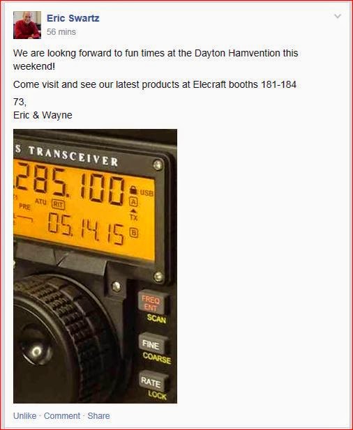
Notice the use of tomorrow's date in the display. Also - the current black chassis radios in the Elecraft line are the K3 and the KX3. Both use black screws on the bezel - not silver. AND the last character before the word "Transceiver" on both radios is a "3" ...... not an "s". Lastly, there's no current radio in the Elecraft line (that I'm aware of) that has that little "down arrow" above the VFO knob.
Seems to me that a major announcement is in the offing for tomorrow. I guess time will tell!
72 de Larry W2LJ
QRP - When you care to send the very least!
Larry Makoski, W2LJ, is a regular contributor to AmateurRadio.com and writes from New Jersey, USA. Contact him at [email protected].
It’s time
To explain what I mean ..... I went down to the shack last night to add some entries to my main logging program from the HamLog app I use when operating portable. I flipped the on switch at 9:30 PM and by the time it had booted up and the logging program had loaded it was about 9:47 PM. 17 minutes is not good. I wanted to start pulling out my hair by then. I think watching paint dry, or grass grow would have been less stressful and more entertaining.
That exercise in frustration drove me to start searching the Web. At work, IBM issued me a Lenovo T410. I still use this model every day. Yes, they are slowly being refreshed out with the newer T440 model, but mine has served me decently well at the job over the last few years. I have found a couple places where I can pick up a refurbed T410 with 4G of RAM, a 250 GB hard drive and Windows 7 Professional in the $150 neighborhood.
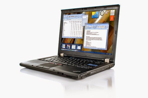
This model has everything I would need. It can hook up to the Internet wirelessly, it has 3 USB ports (need one for the KX3, one for a mouse, and one for an external keyboard), provisions for adding a second VGA monitor and the standard audio ports, so I can do the digital modes, should I ever be inclined to go down that road. Not planning to go there, but you never know. I'll have to dip into savings to acquire one, but having a computer in the shack has almost become a necessity.
Of course, I could always go native and log strictly with paper and pencil, but I don't think the ARRL would accept mailed in Xerox copies of my log for LoTW. Also, I like to keep my eye on QRPSPOTS as well as SOTAWatcher. Can't do that without some kind of computer, although I guess I could always just use my cell phone for those. And having a Telnet DX Cluster at my disposal for confirming that I correctly copied the call of that DX station who was sending at a blistering 45 WPM is a nice thing to have, too. (Was that an "H", or a "5" ? - 37 years of Hamming and my ears still wig out on those two, at times.)
This is another occasion where I'll just have to bite the bullet and take the plunge. Good thing I wasn't planning on going to Dayton.
Oh, and by the way, as long as I mentioned Dayton .... best wishes to all those heading to Ohio for FDIM and Hamvention. May the weather be good, the traffic light and travelling conditions safe - there and back!
72 de Larry W2LJ
QRP - When you care to send the very least!
Larry Makoski, W2LJ, is a regular contributor to AmateurRadio.com and writes from New Jersey, USA. Contact him at [email protected].
 Ham Radio Deluxe |
 W5SWL Electronics |
 Ham Radio Prep |
 KB3IFH QSL Cards  Hip Ham Shirts  HamRadioAuctions HamRadioAuctions Reliance Antennas Reliance Antennas Enigma Shop Enigma Shop |  morseDX  Ni4L Antennas  R&L Electronics R&L Electronics antennas.us antennas.us QRV QRV |
- Matt W1MST, Managing Editor
