 |
 Series Eight Episode Seventeen – Amateur Radio Ebay Reviews (9 August 2015)
In this episode, Martin M1MRB / W9ICQ is joined by Ed Durrant DD5LP ,Martin Rothwell M0SGL and Matthew Nassau 2E0MTT to discuss the latest Amateur / Ham Radio news. Colin M6BOY rounds up the news in brief, and this episodes feature is Ed’s Ebay purchases reviews and antennas.
- Proposed $1000 fine for Identifying Ham Radio Stations
- NoVs Changes for UK Intermediate Amateur Radio Operators
- Amateur Radio Vanity Call Sign Fee to Disappear in September
- Low Cost Device lets Hackers Hijack Satellite and Amateur Radio Satellite Communications
- Special Event Station Host for YOTA Required
- SignaLink and Other USB Digital Interfaces – Huge Bug + Fix for Amateur Radio Digital Modes
- Bogus Ofcom Email targets UK Amateur Radio Operators
- Amateur / Ham Radio Celebration and Promotion of Marine Beacons
- New Radio Initiative Website
- Radiomart.co.uk - New Classifieds Site
- Essex gets 2m D-STAR Amateur Radio Repeater
Colin Butler, M6BOY, is the host of the ICQ Podcast, a weekly radio show about Amateur Radio. Contact him at [email protected].
New versions K1JT weak signal digital modes
Bob, G3WKW, has passed on this information from Joe Taylor K1JT:
“Date: Fri, 07 Aug 2015 16:28:19 -0400
Several people have asked for an update on development of the “Fast modes” in WSJT and WSJT-X. So here’s a brief summary.
First, a review of some relevant terms and motivations. It’s convenient to think of the various WSJT protocols (“modes”) in two groups:
*Slow modes* — JT4, JT9, JT65, and WSPR. These modes are designed for communication with extremely weak signals — often too weak to be heard. Target propagation modes include EME and long-distance troposcatter on HF-and-up bands, and QRP Dxing on the LF, MF, and HF bands. Relevant signal amplitudes are approximately constant over a minute and more, aside from so-called “libration fading” for EME. Transmit/receive sequences are 1 minute for JT4, JT9, and JT65, and 2 minutes for WSPR.
*Fast modes* — JTMS, FSK441, ISCAT, and JT6M — and now also *FSK315* (implemented in WSJT) and *JT9E* through *JT9H* (implemented in WSJT-X. These modes are made for communication with rapidly varying signals:for example, meteor scatter, ionospheric scatter, airplane scatter, and scatter off the International Space Station. The decoders are designed take advantage of short enhancements of signal strength. T/R sequences are 30 seconds (or sometimes even shorter).
Bill, ND0B, has implemented a trial version of FSK315 in WSJT. Think of this mode as FSK441 slowed down to 315 baud; the bandwidth is therefore narrow enough to make the mode legal in the “CW and data” portion of the 10 meter band. Bill and a few others have been experimenting with FSK315 and also ISCAT-A on 10 meters, under dead-band conditions, using meteors and ionospheric scatter propagation.
I have implemented experimental submodes of the JT9 protocol in the program branch WSJT-X v1.6.1. As with JT4 and JT65, letters following the “JT9” designator indicate increased spacings between the FSK tones. Traditional JT9 (now also called JT9A) has tone spacing 1.736 Hz, so the signals used at HF and below have total bandwidth 9*1.736 = 15.6 Hz. The widest of the new submodes, JT9H, has tone spacing 200 Hz and therefore bandwidth 9*200 = 1800 Hz.
When used with the standard 1-minute periods, the wide JT9 submodes should be useful for the same purposes as the wide JT4 submodes: microwave EME, for example, where libration fading can cause Doppler spreading of 100 Hz or more. Used in this way, all JT9 submodes are “slow” modes; they use 1-minute T/R periods and keying rate 1.736 baud, and they send the full 85-symbol message protocol in 85/1.736 = 48.96s.
Optionally, the wide JT9 submodes can now also use “fast” keying rates equal to their tone spacing. “Fast JT9H”, for example, uses keying rate 200 baud, so the full message protocol is transmitted in 85/200 = 0.425s. The message is sent repeatedly for the full Tx period, in the same way as done for the other fast modes.
The fast JT9 submodes should be very effective for meteors and ionoscatter propagation, especially on the 6 meter band. Sensitivity should be similar to ISCAT, or perhaps slightly better. Because JT9 includes strong forward error correction, decoding results are like those for all the slow modes: you should see messages exactly as they were transmitted, or nothing at all.
Tests of the fast JT9 submodes are currently under way, with excellent results.
— 73, Joe, K1JT”
Roger Lapthorn, G3XBM, is a regular contributor to AmateurRadio.com and writes from Cambridge, England.
So just how sporadic is sporadic E (Es)?
Time and again I have been struck by just how unsporadic Es is. OK, good days are random but there seems to be a pattern that more northerly and Scandinavian stations on 10m and 6m are better later in the day and later in the season. I actually wonder if these more northerly reports really are Es at all. There is every chance I am totally wrong, but I have noticed this over several summers and I question that Es is truly “sporadic”. I’d be interested to hear the views of others on this.
One thing is certain: we still have a great deal to learn about E-layer DX propagation. Es is certainly a fact on many summertime EU QSOs on the higher HF bands and 6m, but I am sure the multi-hop explanation for some very long distance QSOs is not right.
Roger Lapthorn, G3XBM, is a regular contributor to AmateurRadio.com and writes from Cambridge, England.
Summits On The Air at Central States VHF
Recently I had the opportunity to speak about portable, mountaintop VHF operating at the Central States VHF Society Conference in Denver. A key part of my presentation was the Summits On The Air program, portable VHF equipment, VHF contests and other operating events.
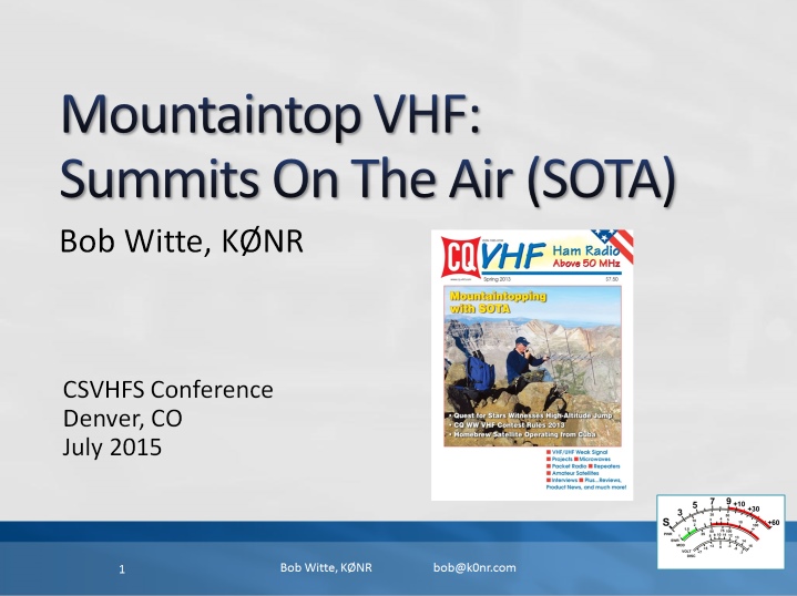 The presentation slides are available here in pdf format. I also submitted a paper on the same topic to the conference a paper on the same topic to the conference proceedings.
73, Bob K0NR
The post Summits On The Air at Central States VHF appeared first on The KØNR Radio Site.
Bob Witte, KØNR, is a regular contributor to AmateurRadio.com and writes from Colorado, USA. Contact him at [email protected].
Straight Key Century Club’s Weekend Sprintathon
 Can't wait 'til New Year's Eve's Straight Key Night? Enjoy CW as it has been sent since the earliest days of Amateur Radio in the SKCC Weekend Sprintathon! The SKCC regularly celebrates the joy of CW ... sent by either hand key or by bug:
The SKCC WES aims to bring together operators with different skill levels in a regularly scheduled, informal operating event lasting 36 hours. The event starts at 1200 UTC on the Saturday following the 6th of each month and ends at 2359 UTC on Sunday. Participants can operate for a total of no more than 24 hours. This event runs from 1200 UTC Aug. 8 to 23:59 UTC Aug. 9.
Non-members are encouraged to join in on the fun and, better yet, get an SKCC number by signing-up. Most of the action will congregate around the SKCC watering-hole frequencies:
Participants may sprint on 160-6 meters, excluding the WARC bands (60, 30, 17, and 12 meters). Suggested frequencies are on or around the SKCC calling frequencies: 1.820, 3.550, 7.055 and 7.114, 14.050, 21.050 and 21.114, 28.050 and 28.114, and 50.090 Mhz. K3UK's sked page or other spotting tools are permitted for this event.
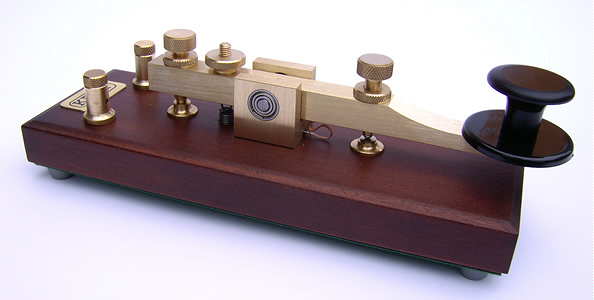
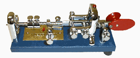
I'll be on 20m for a few hours with my single 6L6 Tri-tet crystal oscillator running about 10 watts ... hopefully within a few KHz of 14.050, doubling from a 40m crystal along with my faithful Vibroplex, purchased as a teenager back in the early 60's.
For all of the details, visit the SKCC WES Rules page here ... so put away your keyers and have some real old fashioned radio fun.
Steve McDonald, VE7SL, is a regular contributor to AmateurRadio.com and writes from British Columbia, Canada. Contact him at [email protected].
Our Amazing Sun and HF Radio Signal Propagation
Space Weather. The Sun-Earth Connection. Ionospheric radio propagation. Solar storms. Coronal Mass Ejections (CMEs). Solar flares and radio blackouts. All of these topics are interrelated for the amateur radio operator, especially when the activity involves the shortwave, or high-frequency, radiowave spectrum.
Learning about space weather and radio signal propagation via the ionosphere aids you in gaining a competitive edge in radio DX contests. Want to forecast the radio propagation for the next weekend so you know whether or not you should attend to the Honey-do list, or declare a radio day?
In the last ten years, amazing technological advances have been made in heliophysics research and solar observation. These advances have catapulted the amateur radio hobbyist into a new era in which computer power and easy access to huge amounts of data assist in learning about, observing, and forecasting space weather and to gain an understanding of how space weather impacts shortwave radio propagation, aurora propagation, and so on.
I hope to start “blogging” here about space weather and the propagation of radio waves, as time allows. I hope this finds a place in your journey of exploring the Sun-Earth connection and the science of radio communication.
With that in mind, I’d like to share some pretty cool science. Even though the video material in this article are from 2010, they provide a view of our Sun with the stunning solar tsunami event:
On August 1, 2010, the entire Earth-facing side of the sun erupted in a tumult of activity. There was a C3-class solar flare, a solar tsunami, multiple plasma-filled filaments of magnetism lifting off the stellar surface, large-scale shaking of the solar corona, radio bursts, a coronal mass ejection and more!
At approximately 0855 UTC on August 1, 2010, a C3.2 magnitude soft X-ray flare erupted from NOAA Active Sunspot Region 11092 (we typically shorten this by dropping the first digit: NOAA AR 1092).
At nearly the same time, a massive filament eruption occurred. Prior to the filament’s eruption, NASA’s Solar Dynamics Observatory (SDO) AIA instruments revealed an enormous plasma filament stretching across the sun’s northern hemisphere. When the solar shock wave triggered by the C3.2-class X-ray explosion plowed through this filament, it caused the filament to erupt, sending out a huge plasma cloud.
In this movie, taken by SDO AIA at several different Extreme Ultra Violet (EUV) wavelengths such as the 304- and 171-Angstrom wavelengths, a cooler shock wave can be seen emerging from the origin of the X-ray flare and sweeping across the Sun’s northern hemisphere into the filament field. The impact of this shock wave may propelled the filament into space.
This movie seems to support this analysis: Despite the approximately 400,000 kilometer distance between the flare and the filament eruption, they appear to erupt together. How can this be? Most likely they’re connected by long-range magnetic fields (remember: we cannot see these magnetic field lines unless there is plasma riding these fields).
In the following video clip, taken by SDO AIA at the 304-Angstrom wavelength, a cooler shock wave can be seen emerging from the origin of the X-ray flare and sweeping across the sun’s northern hemisphere into the filament field. The impact of this shock wave propelled the filament into space. This is in black and white because we’re capturing the EUV at the 304-Angstrom wavelength, which we cannot see. SDO does add artificial color to these images, but the raw footage is in this non-colorized view.
The followling video shows this event in the 171-Angstrom wavelength, and highlights more of the flare event:
The following related video shows the “resulting” shock wave several days later. Note that this did NOT result in anything more than a bit of aurora seen by folks living in high-latitude areas (like Norway, for instance).
This fourth video sequence (of the five in the first video shown in this article) shows a simulation model of real-time passage of the solar wind. In this segment, the plasma cloud that was ejected from this solar tsunami event is seen in the data and simulation, passing by Earth and impacting the magnetosphere. This results in the disturbance of the geomagnetic field, triggering aurora and ionospheric depressions that degrade shortwave radio wave propagation.
At about 2/3rd of the way through, UTC time stamp 1651 UTC, the shock wave hits the magnetosphere.
This is a simulation derived from satellite data of the interaction between the solar wind, the earth’s magnetosphere, and earth’s ionosphere. This triggered aurora on August 4, 2010, as the geomagnetic field became stormy (Kp was at or above 5).
While this is an amazing event, a complex series of eruptions involving most of the visible surface of the sun occurred, ejecting plasma toward the Earth, the energy that was transferred by the plasma mass that was ejected by the two eruptions (first, the slower-moving coronal mass ejection originating in the C-class X-ray flare at sunspot region 1092, and, second, the faster-moving plasma ejection originating in the filament eruption) was “moderate.” This event, especially in relationship with the Earth through the Sun-Earth connection, was rather low in energy. It did not result in any news-worthy events on Earth–no laptops were fried, no power grids failed, and the geomagnetic activity level was only moderate, with limited degradation observed on the shortwave radio spectrum.
This “Solar Tsunami” is actually categorized as a “Moreton wave”, the chromospheric signature of a large-scale solar coronal shock wave. As can be seen in this video, they are generated by solar flares. They are named for American astronomer, Gail Moreton, an observer at the Lockheed Solar Observatory in Burbank who spotted them in 1959. He discovered them in time-lapse photography of the chromosphere in the light of the Balmer alpha transition.
Moreton waves propagate at a speed of 250 to 1500 km/s (kilometers per second). A solar scientist, Yutaka Uchida, has interpreted Moreton waves as MHD fast-mode shock waves propagating in the corona. He links them to type II radio bursts, which are radio-wave discharges created when coronal mass ejections accelerate shocks.
I will be posting more of these kinds of posts, some of them explaining the interaction between space weather and the propagation of radio signals.
For live space weather and radio propagation, visit http://SunSpotWatch.com/. Be sure to subscribe to my YouTube channel: https://YouTube.com/NW7US.
The fourth video segment is used by written permission, granted to NW7US by NICT. The movie is copyright@NICT, Japan. The rest of the video is courtesy of SDO/AIA and NASA. Music is courtesy of YouTube, from their free-to-use music library. Video copyright, 2015, by Tomas Hood / NW7US. All rights reserved.
Visit, subscribe: NW7US Radio Communications and Propagation YouTube Channel
Windows 10
I’ve earned my living in the fascinating world of information technology for many years. The first Microsoft OS which I remember using was Windows 3.0 and since Windows 3.1 I’ve professional supported just about each version published.
My main shack PC is a 3 years old desktop PC and it’s been running Windows 7 since I built it. Before that I had been running Windows XP on an even older machine. While both OS versions supported my enjoyment of the amateur radio hobby, I’ve been very pleased with what Windows 7 had become. Even at the professional level, I find Windows 7 to be a very stable and easy to support OS in the corporate arena.
Like most everyone else, I had been carefully watching the news regarding Windows 10. Back to my professional experience, we moved away from Windows XP as a standard about 3 years ago and have been deploying all employee PC’s (mostly laptops) with Windows 7. We skipped Windows 8 (just as we did with Vista) and our long term plan will be to begin moving to Windows 10 at some point in the future.
Anyway, as I stated….Windows 7 is what I use for all my home PC’s and it’s worked out very well. My main shack PC which I use to perform all logging (contest and otherwise) along with digital modes and rig control works great. This machine logged a QSO for each and every day in 2012 and half of 2014. It’s just a solid machine. However, I must admit that I found myself a bit intrigued by what other hams had been posting about their Windows 10 upgrade experience.
However, I must admit that other than testing new software in my professional role….I have tried to get out of the business of living on the bleeding/cutting edge of technology. Meaning, while I very much consider myself a geek and I truly love to have the latest and greatest gadgets…I’ve generally followed the rule of never upgrading to a new Operating System until the first service pack has been released. Even then I proceed with caution.
But as Microsoft tends to put out a great OS every other version and a not so great OS the other times (Great OS = Windows 2000, Windows XP, Windows 7) (Not so great OS = Windows ME, Vista, Windows 8.x) I knew Windows 10 was going to be in the great category and as I said I had been hearing good things from other hams. So I decided to take the plunge.
After spending time backing up my important files (HRD logbook, all application source files, documents, pictures etc.) I started the upgrade process. Now I must admit that I really don’t like the upgrade from one OS to another process. Additionally, I’ve never had good luck with it. Generally it is almost always better to do a clean install of an OS on a freshly formatted hard drive. But I figure I didn’t have anything to lose. So upgrade we go….
After about 30 minutes my system restarted and I said goodbye to Windows 7 and hello to Windows 10. Of course my main areas of concern was whether my amateur radio apps would all work. I wanted to make sure my log was working and that I could upload to LoTW, eQSL and Club Log. I also checked to make sure rig control worked across all my connected rigs via their USB Serial Cables. All check and good to go. I also quickly checked to make sure other contest logging software worked.
I have nothing negative to report about my Windows 10 upgrade experience. From what I can see (and this is my non-professional opinion as I’ve not spent enough time testing in the corporate environment) but Windows 10 might very well be the absolute best OS Microsoft has developed and best of all….It’s Free!
Just for the record. While I said I had nothing to lose by trying the upgrade, this machine has been progressively getting slower and slower over the past few months. So much so that I had actually planned on performing a rebuild. The upgrade from Windows 7 to Windows 10 did slightly improve my sluggish performance, but I think I’ll most likely do a complete rebuild in the coming weeks.
So should you upgrade to Windows 10? I believe only you can really answer that question. If you are eligible and you have hardware that will run it…I would say go for it. If you don’t see the option to do the upgrade in your system tray you can go to this Microsoft page and start the process.
I’ll be sure to provide additional updates on my Windows 10 experience, but for now I’m pleased (really pleased) with what I see.
Until next time…
73 de KD0BIK
P.S. I’m having a blast easing back into the hobby. I am wrapping my content for the next PARP episode and looking forward to recording it and getting it out to all of you. Thank you for your continued friendship.
Jerry Taylor, KD0BIK, is a regular contributor to AmateurRadio.com and writes from Colorado, USA. He is the host of the Practical Amateur Radio Podcast. Contact him at [email protected].
 Ham Radio Deluxe |
 W5SWL Electronics |
 Ham Radio Prep |
 KB3IFH QSL Cards  Hip Ham Shirts  HamRadioAuctions HamRadioAuctions Reliance Antennas Reliance Antennas Enigma Shop Enigma Shop |  morseDX  Ni4L Antennas  R&L Electronics R&L Electronics antennas.us antennas.us QRV QRV |
- Matt W1MST, Managing Editor
