 |
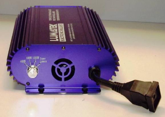
 More ‘Hydroponic’ RF
 |
| courtesy: arrl.org |
Some of the test products were ordered and purchased through Amazon and through Sears ... the ARRL's thorough report makes it obvious that rules are being ignored and amateurs are paying the price.
“The level of conducted emissions from [these devices] is so high that, as a practical matter, one RF ballast operated in a residential environment would create preclusive interference to Amateur radio HF communications throughout entire neighborhoods,” ARRL General Counsel Chris Imlay, W3KD, wrote in each complaint. The devices exceeded conducted emission limits under all test conditions, “sometimes by extreme margins, throughout most of the HF range ...”
In a similar vein as its recent complaint about marketing of certain RF lighting devices by The Home Depot, the ARRL pointed out that there were no FCC labels on two of the devices mentioned nor any FCC compliance information “anywhere in the documentation, or in or on the box, or on the device itself,” in violation of FCC Part 18 rules.
The League asked the FCC to require removal of all such illegal “grow light” devices from retail sale and marketing and the recall of those devices already sold or available for retail sale, and it said the device importers should be subject to a forfeiture proceeding.
With the proliferation of both legal and illegal 'hydroponic' operations, this kind of QRN is probably just the tip of the iceberg. It's good to see the ARRL slowly pounding away at the rule-breakers on behalf of American amateurs.
I see these same devices being sold on E-Bay, where presumably, they could be purchased worldwide and installed anywhere. As well, several of the U.S. online dealers state "We ship to Canada" ... just great.
Hopefully Industry Canada and RAC are gearing-up for the fight.
Steve McDonald, VE7SL, is a regular contributor to AmateurRadio.com and writes from British Columbia, Canada. Contact him at [email protected].
Amateur Radio Weekly – Issue 71

Amateur Radio Parity Act has 93 cosponsors
ARRL Headquarters has forwarded 3,433 letters to 402 individual US House members, seeking their cosponsorship of H.R. 1301.
ARRL
Coming soon: 146.52 MHz in ARRL VHF contests
Brian Mileshosky N5ZGT, ARRL Director of the Rocky Mountain Division, reported that the ARRL has decided to remove the prohibition of 146.52 MHz in VHF contests.
K0NR
Why 30 Meter APRS?
A case study on 30m APRS vs the 2m APRS network.
The Kentucky Packet Network
Comparing RTTY, PSK and MFSK
Using the ARRL field day test message to compare RTTY, PSK and MFSK digital modes.
HamRadio.me
FUNcube Certificate of Achievement and QSL Card
Those who have successfully received telemetry from FUNcube-1 and uploaded it to the Data Warehouse are able to download these documents.
AMSAT UK
Understanding LF and HF Propagation (PDF)
This PDF is a series of features that formed a good introduction to the topic.
G0KYA, G3NYK
Raspberry Pi packet/digital mode open hardware
Ham Radio sound card interface for the Raspberry Pi or other microcontrollers.
Reddit
Android balloon tracker and modem app
Ground tracking app for high altitude balloons, complete with RTTY modem, offline mapping, online distributed listener integration, chase car location reporting and more.
Google Play
Arduino CW decoder
This is arguably the simplest part of the project. I simply downloaded the sketch and uploaded it to the Arduino.
Amateurradio.com
Icom America club station revealed
I’m pleased to report that a number of our employees are regularly getting on the air and we’re looking forward to activating a few contests as well.
Icom
How to
Google Earth with NWS and APRS using KML
I wanted to find an easy way to integrate mapping, radar data, and APRS tracking data for SkyWARN events.
Robert Andrews
Simple one-chip regenerative receiver
You might be surprised that you can convert an audio amplifier to a receiver using just a handful of components.
Hackaday
Amateur Radio Weekly is curated by Cale Mooth K4HCK. Sign up free to receive ham radio's most relevant news, projects, technology and events by e-mail each week at http://www.hamweekly.com.
Amateur Radio Newsline Report 1970 July 31 2015
- RADIO REGULATION: TWO FCC CRACKDOWNS
- UPDATE: DATE SET TO END VANITY FEE
- RADIO RECIPROCITY
- PIMA COUNTY GETS PREPARED
- IRELAND'S NODE FOR NEWS
- DEVELOPING NATIONS GET GRANTS
- CASSIOPE FIELD DAY RESULT
- STUDENTS BREAK FOR LAUNCH
- ALL'S FAIR IN RADIO AND WAR
- RADIO RESEARCH: HAARP GETS A TRANSFER
- DX NEWS
- FROM MISSILES TO A MISSION
Stunning Video of the Sun Over Five Years, by SDO
Watch this video on a large screen. (It is HD). Discuss. Share.
This video features stunning clips of the Sun, captured by SDO from each of the five years since SDO’s deployment in 2010. In this movie, watch giant clouds of solar material hurled out into space, the dance of giant loops hovering in the corona, and huge sunspots growing and shrinking on the Sun’s surface.
April 21, 2015 marks the five-year anniversary of the Solar Dynamics Observatory (SDO) First Light press conference, where NASA revealed the first images taken by the spacecraft. Since then, SDO has captured amazingly stunning super-high-definition images in multiple wavelengths, revealing new science, and captivating views.
February 11, 2015 marks five years in space for NASA’s Solar Dynamics Observatory, which provides incredibly detailed images of the whole Sun 24 hours a day. February 11, 2010, was the day on which NASA launched an unprecedented solar observatory into space. The Solar Dynamics Observatory (SDO) flew up on an Atlas V rocket, carrying instruments that scientists hoped would revolutionize observations of the Sun.
Capturing an image more than once per second, SDO has provided an unprecedentedly clear picture of how massive explosions on the Sun grow and erupt. The imagery is also captivating, allowing one to watch the constant ballet of solar material through the sun’s atmosphere, the corona.
The imagery in this “highlight reel” provide us with examples of the kind of data that SDO provides to scientists. By watching the sun in different wavelengths (and therefore different temperatures, each “seen” at a particular wavelength that is invisible to the unaided eye) scientists can watch how material courses through the corona. SDO captures images of the Sun in 10 different wavelengths, each of which helps highlight a different temperature of solar material. Different temperatures can, in turn, show specific structures on the Sun such as solar flares or coronal loops, and help reveal what causes eruptions on the Sun, what heats the Sun’s atmosphere up to 1,000 times hotter than its surface, and why the Sun’s magnetic fields are constantly on the move.
Coronal loops are streams of solar material traveling up and down looping magnetic field lines). Solar flares are bursts of light, energy and X-rays. They can occur by themselves or can be accompanied by what’s called a coronal mass ejection, or CME, in which a giant cloud of solar material erupts off the Sun, achieves escape velocity and heads off into space.
This movie shows examples of x-ray flares, coronal mass ejections, prominence eruptions when masses of solar material leap off the Sun, much like CMEs. The movie also shows sunspot groups on the solar surface. One of these sunspot groups, a magnetically strong and complex region appearing in mid-January 2014, was one of the largest in nine years as well as a torrent of intense solar flares. In this case, the Sun produced only flares and no CMEs, which, while not unheard of, is somewhat unusual for flares of that size. Scientists are looking at that data now to see if they can determine what circumstances might have led to flares eruptions alone.
Scientists study these images to better understand the complex electromagnetic system causing the constant movement on the sun, which can ultimately have an effect closer to Earth, too: Flares and another type of solar explosion called coronal mass ejections can sometimes disrupt technology in space as well as on Earth (disrupting shortwave communication, stressing power grids, and more). Additionally, studying our closest star is one way of learning about other stars in the galaxy.
Goddard built, operates and manages the SDO spacecraft for NASA’s Science Mission Directorate in Washington, D.C. SDO is the first mission of NASA’s Living with a Star Program. The program’s goal is to develop the scientific understanding necessary to address those aspects of the sun-Earth system that directly affect our lives and society.
https://www.youtube.com/watch?v=zXN-MdoGM9g
Visit, subscribe: NW7US Radio Communications and Propagation YouTube Channel
A Solar flare, A CME, A Proton Storm: Magnitude M2.5 X-ray Flare
Watch this amazing explosion on the Sun. From sunspot complex 1226-1227 comes an X-ray Flare peaking at a magnitude of M2.5 at 0640 UTC on 7 June, 2011.
Source: https://www.youtube.com/watch?v=KQMrRu8BWDo
This X-ray flare hurled a massive coronal mass ejection (CME) toward the Earth. This not-squarely Earth-directed CME is moving at 1400 km/s according to NASA models. The CME did not deliver even a noticeable glancing blow to Earth’s magnetic field late June 8th or June 9th.
What can be seen clearly in this movie is one of the most spectacular prominence eruptions ever observed. In fact, one could call it a “prominence explosion”. The prominence material expanded to a volume some 75 times as big across as the earth!
This X-ray flare also triggered an S1-level solar radiation storm, causing a long-lasting polar cap absorption (PCA) event. A polar cap absorption (PCA) event affects the propagation of a shortwave radio signal as it makes its way over the polar regions. In short, radio communications on lower shortwave radio frequencies become more difficult, as those radio signals are absorbed by the ionosphere (in the D-region) over the polar regions.
What does this mean in real-world communications? Trans-polar airline pilots may find it more difficult to communicate with regional air traffic control, shortwave radio listeners who want to hear a broadcast from a country by receiving a transmission from a country by way of a transmission beamed over the pole (like, from Europe into the USA via the North Pole), or other such communications, will find those signals all but gone. The stronger the PCA event, the higher the frequencies absorbed over the polar regions, with the greatest absorption occurring at the lower frequencies.
This movie spans the period of time from 0300 UTC through 1556 UTC, and is composed of the 171-Angstrom, 304-Angstrom, and 335-Angstrom wavelength views as captured by the filters of the Solar Dynamics Observatory (SDO) Atmospheric Imaging Assembly (AIA). In this movie, the AIA instruments capture the Sun’s extreme ultraviolet light and reveal a very large eruption of cool gas. It is somewhat unique because at many places in the eruption there seems to be even cooler material–at temperatures less than 80,000 K.
The following is a linked video that is part of this event: http://www.youtube.com/watch?v=L4CsjcUGoaw
Watch as we zoom out to see a total view of the June 7, 2011 moderately-powerful X-ray Flare and Prominence Eruption. This movie will give you a full perspective of the immense size of this prominence eruption as it spews out away from the Sun.
The X-ray Flare peaked at a moderate magnitude of M2.5 at 0640 UTC, but unleashed a huge prominence eruption. The massive cloud of plasma was ejected out into interplanetary space, but missed the Earth. This movie stars with a “close-up” view by the Solar Dynamics Observatory at a combined wavelength view at 94 and 304 Angstroms. Then, the movie views the event further back through the eyes of the COR1 spacecraft (with the SDO AIA 304 image superimposed in the middle). Next, we zoom out to the COR2 spacecraft and superimpose the COR1 and SDO views. Then, we zoom further back to the H1 view… and finally look again at the event close-up.
More info: http://sunspotwatch.com/
Google Plus:
http://g.nw7us.us/gplus_spacewx
Facebook:
http://www.facebook.com/spacewx.hfradio
http://www.facebook.com/NW7US
Twitter:
@hfradiospacewx
@NW7US
Source: SDO AIA NASA SOHO
Visit, subscribe: NW7US Radio Communications and Propagation YouTube Channel
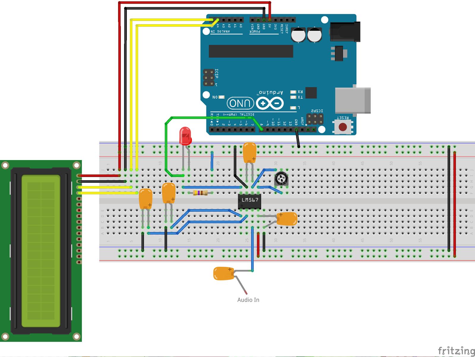
CW decoder – The Arduino
 This is arguably the simplest part of the project. As mentioned Budd Churchward had created a series of videos on how he wrote the Sketch, created a PCB and published his code. (Budd’s Sketch is available here)
Dan Trudgian, MØTGN, is a regular contributor to AmateurRadio.com and writes from Wiltshire, England. He's a radio nut, IT guru, general good guy and an all round good egg. Contact him him here.
CW decoder – The electronics

Dan Trudgian, MØTGN, is a regular contributor to AmateurRadio.com and writes from Wiltshire, England. He's a radio nut, IT guru, general good guy and an all round good egg. Contact him him here.
 Ham Radio Deluxe |
 W5SWL Electronics |
 Ham Radio Prep |
 KB3IFH QSL Cards  Hip Ham Shirts  HamRadioAuctions HamRadioAuctions Reliance Antennas Reliance Antennas Enigma Shop Enigma Shop |  morseDX  Ni4L Antennas  R&L Electronics R&L Electronics antennas.us antennas.us QRV QRV |
- Matt W1MST, Managing Editor
