 |
 Drawing PCBs With ‘MS Paint’
I recently had an inquiry about using 'MS Paint' for drawing PC board layouts. Although there are several freeware programs available for designing and drawing PC layouts, the ones I have tried had onerous learning curves. I also found that unless I was designing boards fairly regularly, I would have to go back and re-learn many of the functions each time I used the program. If you are regularly making a lot of boards, then these programs are certainly the way to go as they are packed with every feature you might need.
On the other hand, MS Paint meets all of my requirements and is simple to use ... I like simple. Although some might turn up their noses at MS Paint, I have found it to be a powerful and underestimated software tool. Here are some of the things that you might want to remember if drawing a PC layout with 'Paint'.
1. Take the time to read the built-in HELP and USING files. It doesn't take long to learn all of the functions along with some of the shortcuts.
2. Always draw with the IMAGE ... DRAW OPAQUE function turned off (unchecked). Do this first. This way, lines can go as close as you want without any blocking or overlapping. Try it the other way and you can see what happens.
3. If you are working with IC's, take the time to make a 'master' pattern that can be saved and copied anytime that you need it. A 16-pin layout can by used for 14 and 8 pin IC's by copying and pasting it and then erasing the unwanted pins. I can send you one via email if you contact me.

4. Similarly, once you have established the correct pad spacing for certain capacitors or resistor sizes, copy and save them for future use. Finding the correct spacing will require a few trial printouts so you can measure the exact gap.
5. For detailed work, use the VIEW ... ZOOM...CUSTOM function to magnify the layout. This also allows you to use a grid if you find this helpful.
6. Never SAVE your layout while in ZOOM mode as you can't go back to the original size when you re-load your plan. I learned this the hard way.
7. For drawing perfectly straight lines, squares or round circles, hold the SHIFT key down when drawing the element.
8. For large areas of copper (groundplanes), outline the area then choose the FILL symbol to create the area.
9. With a little planning, you can almost always avoid jumpers to make a crossover connection, unless your circuit is very complex.
10. When you make a mistake, just use the EDIT ...UNDO command. You can go back several steps with this helpful function.
11. I will often draw a thin line between to pads to see if they are on the same level ... and then UNDO the line once I have checked.
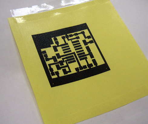
12. Always SAVE your layout as a Monochrome Bitmap with the FILE ... SAVE AS function. Using some of the other modes will create less than solid blacks and some random pixels that can lead to etching problems.
13. If using the 'toner iron-on' method of etching, set your printer options to the highest resolution (mine is 1200 dpi) and then choose the darkest 'print' option. You want as much toner thickness as possible. Note that this method works only with laser / toner printers and not the ink-jet / bubble types.
14. For the iron-on transfer paper, I have had good success with the shiny yellow transfer paper widely available on E-Bay, usually with free shipping. I get the best results when pre-heating the PCB in the toaster oven before ironing-on the pattern ... not too hot to touch however.
If you just build the occasional PC board, you might find using MS Paint worthy of a try. It has been meeting my needs for many many years and once you have done a few, unlike some PC software, it doesn't take long to build a new board without having to learn how to use it all over again.
Steve McDonald, VE7SL, is a regular contributor to AmateurRadio.com and writes from British Columbia, Canada. Contact him at [email protected].
Amateur Radio Weekly – Issue 78

Why public service-oriented Hams should participate in contests
Radio contests are training that improves our abilities elsewhere in Amateur Radio.
Social Contest Club
FreeDV voice keyer and spotting demo
FreeDV has a low bit rate text message stream that allows you to send information such as your call-sign and location.
Rowetel
Wire antennas in trees
Choosing a wire antenna system is one thing. Finding somewhere to put it up is another. Particularly if you’re short on supporting structures around the home environment.
Delta Alfa
Russian military in 7 and 14 MHz Ham Radio bands
The latest IARU Monitoring System newsletter reports Russian Military traffic in the amateur radio 7 and 14 MHz bands has increased.
Southgate
Meet the preppers who are ready for the next massive solar storm
Another source emphasized the value of hunting down older, “tube type” communications gear. “Modern amateur radio gear is hugely susceptible to EMP.”
Gizmodo
FM/VHF operating guide
This guide is intended to assist new amateur radio operators in figuring out what VHF FM and repeater operation is all about.
K0NR
Signal Identification Guide
This wiki is intended to help identify radio signals through example sounds and waterfall images.
Signal Identification Guide
1090 MHz bandpass filter from FlightAware
FlightAware.com is a website that aggregates ADS-B aircraft location data from various contributors.
RTL-SDR.COM
Turn your current transceiver into an SDR
The MDSR software performs all of the demodulation, filtering (both radio frequency and audio frequency), signal enhancement (equalization and binaural presentation).
MDSR
We need a better UHF connector
The venerable UHF connector was developed in the 1930’s. The UHF connector suffers from two problems.
amateurradio.com
Video
DMR TYT MD-380 programming tutorial
A guide aimed at people new to DMR, showing how to program an amateur repeater and a simplex channel.
YouTube
Solar powered HF Ham Radio portable system
Zamp 40 watt Portable Solar Charging System ZS-40-P, 80-6 Meter-Alpha EZ-Military Antenna, ICOM-IC-718 HF-Ham Radio, LDG-IT-100-AutoTuner, and a 18AH-Werker-AGM Battery.
YouTube
Amateur Radio Weekly is curated by Cale Mooth K4HCK. Sign up free to receive ham radio's most relevant news, projects, technology and events by e-mail each week at http://www.hamweekly.com.
We Need a Better UHF Connector
The venerable UHF connector was developed in the 1930’s. It has withstood the test of time and for the most part is a good connector for HF and VHF applications in amateur radio. It’s fairly inexpensive, has somewhat intuitive assembly, and is mechanically robust. From an RF perspective it’s not bad at HF and VHF, but despite the UHF name it exhibits an impedance bump at UHF frequencies and is usually avoided for UHF applications.
The UHF connector suffers from two problems, in my opinion. One is that it’s not weatherproof. You absolutely, positively should not have a UHF connector outdoors without weatherproofing. If you do not weatherproof it, you will have water intrusion into the connector and probably into the braid of the coaxial cable. Weather. Proof. It. Connectors like the N connector (a very common connector in commercial RF applications) which sports rubber gaskets on the mating surface and within the body of the connector are weatherproof, although it’s still advisable to use weatherproofing with the N connector.
The second issue is the difficulty in soldering the braid. The holes in the body of the UHF connector expose the ground braid and you’re supposed to solder through these holes to make a positive connection between the braid and the connector body, and provide mechanical strength and stability. Some folks pre-tin the ground braid before inserting it into the body, others do not. You need a high wattage iron to do this properly and the heat required can melt the dielectric in the process. I think many people don’t solder this well and some avoid doing it at all.
K3LR demonstrated an alternative method of soldering the braid to the PL-259 in this video:
I’ve tried this technique and for the most part it works. (I prefer to use heat-shrink tubing around the exposed soldered braid.) However, as you can see from the video it’s not pretty as it requires increasing the diameter of the dielectric with electrical tape, and there is not a snug fit between the connector body and the soldered braid and the coax jacket. This technique in my opinion does provide a better braid electrical connection than most mere mortals can accomplish using the proper solder hole method, as the connector is intended to be used.
I think a PL-259 connector needs to be designed for this technique. The body of the connector should have a smaller inner diameter in order to fit the diameter of the RG-213 dielectric. The outer part of the connector body where the braid is soldered to it could be of a smaller diameter as well and perhaps have a gnarled surface in order to promote better adhesion of the solder. I would like to see some sort of rubber gasket employed with the threaded sleeve for some weatherproofing, however I can’t think of a good way to implement this without affecting the electrical connectivity to the body.
Unfortunately I’m more a software guy and not very good at fabricating metal parts. Someone with manufacturing experience could probably design this connector and perhaps make a small fortune. It’s problem waiting to be solved.
Anthony, K3NG, is a regular contributor to AmateurRadio.com.
Amateur Radio Newsline Report 1977 September 18, 2015
- BREAKING NEWS: HAMS HELP AT CALIFORNIA WILDFIRE
- WELCOMING POPE FRANCIS
- CREW BACK HOME ON EARTH
- MARATHON MINUTE MEN
- POW-MIA EVENT WRAPS UP
- SOUTH AFRICAN HALL OF FAME
- PARTY WITH NO RULES
- BACK TO A ROUTE’S ROOTS
- TWO COLLEGE SHACKS DO THEIR HOMEWORK
- LIKE FATHER, LIKE DAUGHTER
- (VERY LOW) POWER TO THE PEOPLE
- THE WORLD OF DX
- CODE OF CONDUCT
QRP commercial rigs
The FT817 successor may be announced at Dayton next year. If correct, this is about 3-4 years too late.
The ICOM IC703 is not being replaced by the 10W version of the IC7300 outside of Japan. Personally, I do not understand the major Japanese manufacturers. Surely there is a worldwide demand for a 5-10W SDR based, radio?
It seems the huge world-wide QRP market is not being well addressed by the Japanese. It is their loss. I think they are all nuts!
Ten-Tec seem to be struggling with their latest Argonaut judging by recent price cuts. See http://www.rkrdesignsllc.com/products/transceivers-receivers/ten-tec-model-539-argonaut-vi-qrp-1-10-watt-transceiver/ .
No, personally I think we are seeing QRPers getting a rough deal of late.
Roger Lapthorn, G3XBM, is a regular contributor to AmateurRadio.com and writes from Cambridge, England.
FT991 price dropping
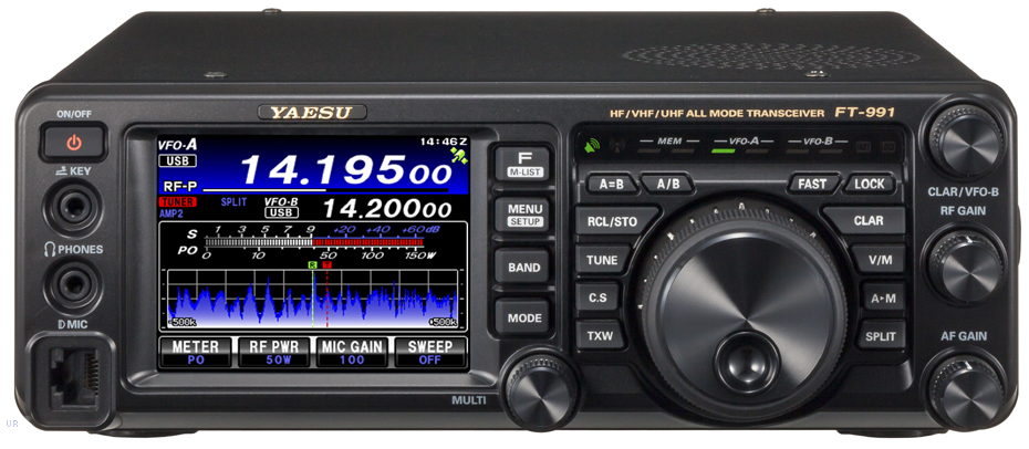 |
| Yaesu FT991 |
MLS are advertising a time limited offer of the FT991 and a bundled SMPSU at £1149.95. Now there will soon be an ICOM competitor albeit with no 2m/70cm but with 4m in the European version (and arguably a better radio?) at less than £1000 in the form of the IC7300.
No, I confidently predict the FT991 will sell for less than £1000 before the year is ended. If you are in the market for a 100W radio it is a toss-up between the IC7300 (SDR based) and the FT991. At the moment, the IC7300 looks better value.
Yaesu may announce a (long awaited) FT817 replacement at Dayton next spring but don’t expect to see units in Europe before autumn 2016 or later, is my bet. The Yen exchange rate has vastly improved (making Japanese goods less expensive to buy) and now the FT991 has a serious rival – result is Yaesu has to drop its price for the FT991 or they lose out. My advise is wait a few months.
Roger Lapthorn, G3XBM, is a regular contributor to AmateurRadio.com and writes from Cambridge, England.
Lightwave-Portable Progress
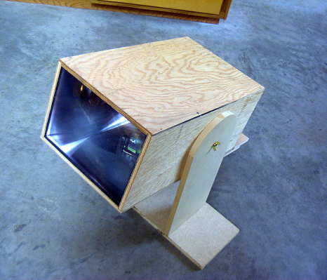
On Tuesday, I completed the plywood enclosure for the new portable lightwave receiver and mounted the optics and the electronics. My plan is to use this here on the island for some clear-air scatter / cloudbounce tests, once suitable listening locations are determined.
As with my main system, I used a homebrew mount capable of movement in three directions.
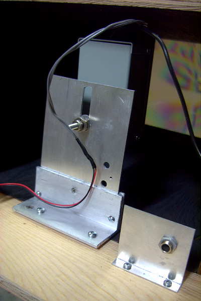
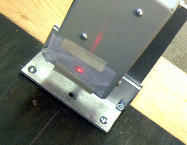
The photodiode needs to be mounted precisely at the focal point of the fresnel lens, and all three directions need to be juggled for correct alignment. Shown below is the setup used on the shop floor for alignment. The signal source is a 1W red LED about ten feet away.
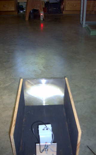
I covered the photodiode with a small piece of paper which made it a lot easier to find the point of sharpest focus. Once this had been found, everything was tightened and, hopefully, locked into position.
I then constructed a simple mount which allows the receiver to be tilted in altitude so it can be set to point at the desired region of sky. Once this was done, there was nothing else I could do but wait for darkness, so that the receiver could be tested.

The fresnel lens used was purchased locally for just $5, so I had my suspicions regarding its optical quality. As well, it is 20% smaller than the bigger lens used in the main lightwave system. The bigger lens is 650 sq.cm compared to the inexpensive 'page-reader' lens of 530 sq.cm. The 2mm thick rigid plastic lens is an 'Enkay 2950-C'. The larger lens has a focal length of 20cm while the page reader has a focal length of 45cm. This gives them 'f' numbers of .78 and 1.6 respectively.
Once it was dark enough, I took the receiver to the ocean side of the house and sat down with the receiver. From here I have a clear view of the mainland coast, on the other side of Strait of Georgia. The nearest point of land on the other side of the Strait is about 20km.
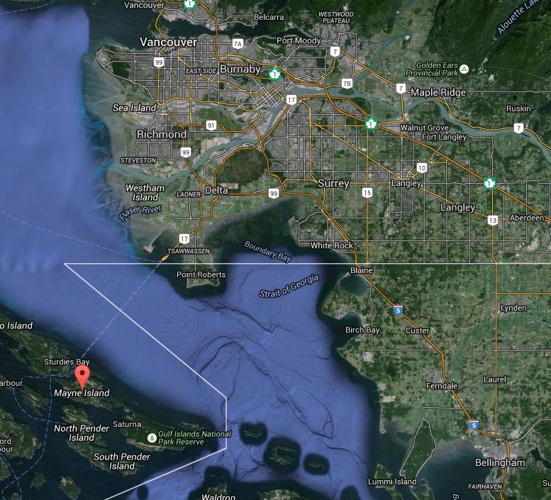 |
| courtesy: https://www.google.ca/maps/ |
To hear similar signals, recorded on my first receiver, go to the links at the bottom of this blog from 2014/08.
The next task will be to determine suitable listening locations here on the island. Unfortunately, the island is dominated with two high (600'+) peaks, one right behind me to the south, which will make it challenging to get a signal from one side to the other. Hopefully I can find a clear spot somewhere that will allow me to shoot a signal over the top ... and of course, the fall weather must co-operate.
 |
| courtesy: https://www.google.ca/maps/ |
Steve McDonald, VE7SL, is a regular contributor to AmateurRadio.com and writes from British Columbia, Canada. Contact him at [email protected].
 Ham Radio Deluxe |
 W5SWL Electronics |
 Ham Radio Prep |
 KB3IFH QSL Cards  Hip Ham Shirts  HamRadioAuctions HamRadioAuctions Reliance Antennas Reliance Antennas Enigma Shop Enigma Shop |  morseDX  Ni4L Antennas  R&L Electronics R&L Electronics antennas.us antennas.us QRV QRV |
- Matt W1MST, Managing Editor
