 |
 Hunting For NDBs In CLE 199
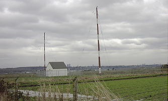 |
| 'ZVR-368kHz' at Vancouver International |
It's time for another CLE (Co-ordinated Listening Event) once again! For you low-frequency buffs, another challenge awaits. This month's activity covers the range of 190 - 1740 kHz.
CLE 199 is an 'A-B-C' activity ... a little different from the norm, and listeners are requested to report NDB's from countries, states or provinces, beginning with the letter A, B & C only. Listeners in western NA will find plenty of targets but it might be a challenge for those on the eastern side.
A list of eligible 'A-B-C' entities can be found at the bottom. Additionally, a list of all of the North American targets in this frequency range can be found in the RNA database, while targets for European DXers will be found here ... either chose the 'Seeklist' button or search for the desired state, province or country for detailed frequency information.
A nice target for this CLE is 'ZVR' (368kHz) shown above. The 20W locator from Vancouver International, has been heard from Hawaii to North Carolina. It is located a little east of YVR, in a boggy farmland region.
From CLE coordinator Brian Keyte (G3SIA) comes the following reminder:
Hello all
Almost time for our 11th 'Countries' Listening Event. Whether you are a
regular, or have never sent a CLE log before, your log will be very welcome.
Days: Friday 23 October - Monday 26 October
Times: Start and end at midday, your local time.
Targets: 'Normal' NDBs (190 - 1740 kHz) - not DGPS, Navtex
or Amateur - located in the Radio Countries whose
codes start with A, B or C.
These are our 2-letter codes for the Provinces/States of Canada and USA
and our 3-letter codes elsewhere, including AUS (Australia) -all its States.
The full list of all qualifying countries is given at the end of this email.
Detailed seeklists are available from the Rxx database - just select
SEEKLIST on the CLE page, http://www.ndblist.info/cle.htm
Martin has also added a 'Seeklist Map' facility there too.
If you are in the east of N. America it may be quite a tough challenge.
Most other listeners should be in luck this time, including several who
usually have a hard time.
Please send your CLE log to the List (no attachments and a plain text email
if possible) with CLE199 at the start of its title. Show on each log line:
# The Date (or Day No. 23 to 26)
# The Time in UTC** (the day changes at 00:00 UTC).
# kHz - the nominal published frequency, if known.
# The Call Ident.
**Many of us will be changing our clocks by one hour this weekend
but UTC time continues without any change.
Please show the above main items FIRST on each line of your log.
Any other optional details such as Country, Location, Distance, etc.
go LATER in the same line.
If you send any interim logs, please also send a 'Final' (complete) log.
Always tell us your own location and brief details of the equipment
that you were using.
Do make sure that your log has arrived by 09:00 UTC on
Wednesday 28 October at the very latest.
I hope to complete making the combined results on that day.
Good listening.
Enjoy the hunt!
Brian
----------------------------------------------------------
From: Brian Keyte G3SIA ndbcle'at'gmail.com
Location: Surrey, SE England (CLE co-ordinator)
----------------------------------------------------------
(Reminder: You could use any one remote receiver for your loggings,
stating its location and owner - with their permission if required.
A remote listener may NOT also use another receiver, whether local
or remote, to obtain further loggings for the same CLE)
These listening events serve several purposes. They:
- determine, worldwide, which beacons are actually in service and on-the-air so the online database can be kept up-to-date
- determine, worldwide, which beacons are out-of-service or have gone silent since the last CLE covering this range
- will indicate the state of propagation conditions at the various participant locations
- will give you an indication of how well your LF/MF receiving system is working
- give participants a fun yet challenging activity to keep their listening skills honed
Final details can be found at the NDB List website, and worldwide results, for every participant, will be posted there a few days after the event. If you are a member of the ndblist Group, results will also be e-mailed and posted there.
The very active Yahoo ndblist Group is a great place to learn more about the 'Art of NDB DXing' or to meet other listeners in your region. There is a lot of good information available there and new members are always very welcome.
If you are contemplating getting started on 630m, listening for NDBs is an excellent way to test out your receive capabilities as there are several NDBs located near this part of the spectrum.
You need not be an ndblist member to participate in the CLEs and all reports, no matter how small, are of much value to the organizers. 'First-time' logs are always VERY welcome!
Reports may be sent to the ndblist or e-mailed to either myself or CLE co-ordinator, Brian Keyte (G3SIA), whose address appears above.
Please ... give the CLE a try ... then let us know what NDB's can be heard from your location! Your report can then be added to the worldwide database to help keep it up-to-date.
EXTRACTS FROM OUR COUNTRY LIST Last revised: 23 Oct 2006
( http://www.ndblist.info/ndbinfo/countrylist.pdf )
SHOWING ALL THE QUALIFYING COUNTRIES FOR THE CLE
NORTH AMERICA:
ALS ALASKA (US state)
BER BERMUDA (UK)
AB Alberta, Canada
BC British Columbia, Canada
AL Alabama, USA
AZ Arizona, USA
AR Arkansas, USA
CA California, USA
CO Colorado, USA
CT Connecticut, USA
CENTRAL AMERICA/CARIBBEAN:
AIA ANGUILLA
ATG ANTIGUA & BARBUDA
ABW ARUBA
BAH BAHAMAS
BRB BARBADOS
BLZ BELIZE
CYM CAYMAN ISLANDS
CTR COSTA RICA
CUB CUBA
ATN NETHERLANDS ANTILLES
BAR ST BARTHELEMY
SOUTH AMERICA:
ARG ARGENTINA
BOL BOLIVIA
BRA BRAZIL
CHL CHILE
CLM COLOMBIA
EUROPE:
ALB ALBANIA
AND ANDORRA
AUT AUSTRIA
AZR AZORES (PORTUGAL)
BRI REAR ISLAND / BJORNOYA (NORWAY)
BLR BELARUS
BEL BELGIUM
BAL BALEARIC ISLANDS (SPAIN)
BIH BOSNIA-HERCEGOVINA
BUL BULGARIA
COR CORSICA (FRANCE)
CZE CZECH REPUBLIC
CVA VATICAN STATE
AFRICA:
ALG ALGERIA
AGL ANGOLA
ASC ASCENSION ISLAND (UK)
BEN BENIN
BOT BOTSWANA
BFA BURKINA FASO
BDI BURUNDI
CAB CABINDA (ANGOLA)
CME CAMEROON
CNR CANARY ISLANDS (SPAIN)
CPV CAPE VERDE
CAF CENTRAL AFRICAN REPUBLIC
CEU CEUTA (SPAIN)
COM COMOROS
COG CONGO-BRAZZAVILLE
COD CONGO-KINSHASA
CTI IVORY COAST
AFS SOUTH AFRICA
AOE WESTERN SAHARA
ASIA:
AFG AFGHANISTAN
ANI ANDAMAN & NICOBAR ISLANDS (INDIA)
ARM ARMENIA
AZE AZERBAIJAN
BHR BAHRAIN
BGD BANGLADESH
BTN BHUTAN
BRU BRUNEI
CBG CAMBODIA
CHN CHINA (PRC)
CHR CHRISTMAS ISLAND (AUSTRALIA)
CYP CYPRUS
BRM MYANMAR (BURMA)
ARS SAUDI ARABIA
CLN SRI LANKA
OCEANIA:
AUI AUSTRAL ISLANDS (FRANCE)
AUS AUSTRALIA ( all States: AT, NW, NN, QD, SA, TA, VI, WE )
CLI CLIPPERTON (FRANCE)
CKH COOK ISLANDS (NORTHERN)
CKS COOK ISLANDS (SOUTHERN)
ANTARCTICA:
ATA ANTARCTICA MAINLAND
Steve McDonald, VE7SL, is a regular contributor to AmateurRadio.com and writes from British Columbia, Canada. Contact him at [email protected].
Digital Voice Balkanization
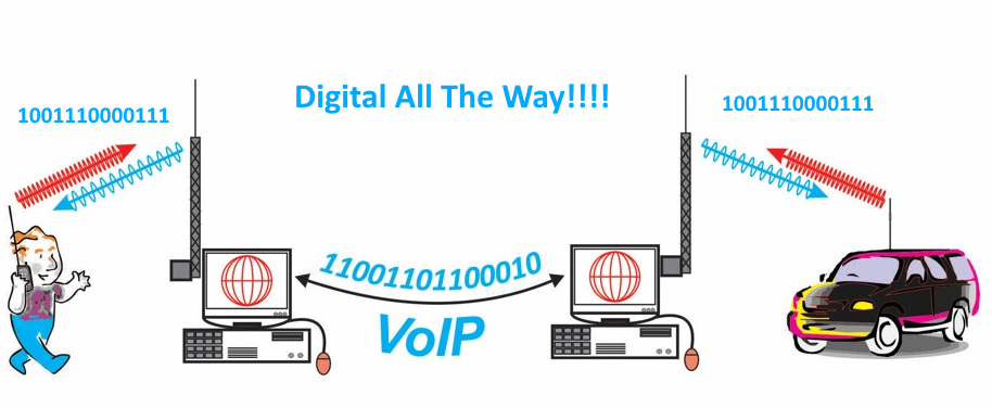 Wouldn’t it be cool if we had one digital communications format for the VHF/UHF amateur bands with all equipment manufacturers offering compatible products? The basic modulation and transport protocol would be standard with manufacturers and experimenters able to innovate on top of that basic capability. There would be plenty of room to compete based on special features but all radios would interoperate at a basic level. You know, kind of like analog FM.
Yeah, we don’t have that. 
73, Bob K0NR
Graphic: Adapted from HamRadioSchool.com
The post Digital Voice Balkanization appeared first on The KØNR Radio Site.
Bob Witte, KØNR, is a regular contributor to AmateurRadio.com and writes from Colorado, USA. Contact him at [email protected].
Setting a Baofeng on FIRE!
I came across this video through the qrz.com forums. K5CLC did some extreme testing of a Baofeng UV-5R, including setting it on FIRE! The results are interesting. Skip to 2:57 to see the flames. I really like my Baofeng HT…not as my primary radio but as the one that is with me when I’m working on the farm, tinkering in the barn, or anytime I’m likely to have dirty hands.
Michael Brown, KG9DW, is a regular contributor to AmateurRadio.com and writes from Illinois, USA. Contact him at [email protected].
Challenging Topband
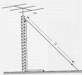 |
| The 'Half-Sloper' |
When I purchased my first house in the suburbs in '74, I was finally able to put up a real antenna ... a 'half-sloper', fed from the top of my new 48' tower, along with an extensive set of radials running along the perimeters of my yard. I also hung both 80 and 40m half-slopers from the same feedpoint, giving me coverage on all three of the low bands.
Once the Japanese manufacturers started adding 160m coverage to the various lines of transceivers, the band really started to get popular, as up until that time, very few commercial transmitters covered 160m. Most of the E.F. Johnsons, the DX-100, and some of the late Drake radios were doing the heavy-lifting unless one was enterprising enough to homebrew or modify a rig for 160.
I immediately set out to work all 50 states from my suburban location, running a pair of 6146's at around 150 watts input. It took me a few winters to get them all, with Rhode Island being the most difficult, at #50.
My 160m W.A.S. certificate was #264.
Conditions always varied with the solar cycle but a surprising amount of DX was worked at my low power level. A couple of the more memorable contacts from those days were with H44IA in the Solomons and with VK9NS, on Norfolk Island.
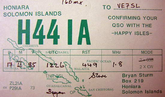
H44IA was worked at 0426 local time in February. I recall calling several JA stations that morning with no response (I always found difficulty working JA on 160) and was more than surprised when the H44 came right back to my response to his CQ.
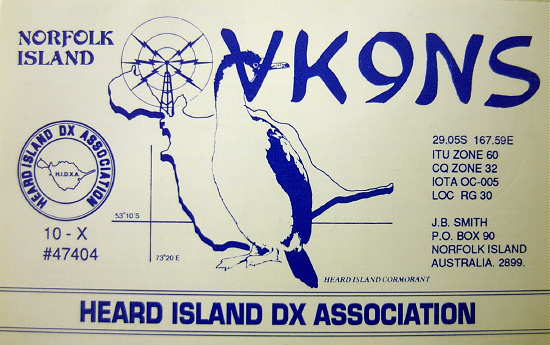
Jim Smith, VK9NS (SK), seemingly spent more time at various exotic locations than at home. Over the years I was able to work him on a number of his Pacific-island expeditions, but it was gratifying to finally catch him from another rare spot ... his home! This contact was in mid-July, right at sunrise.
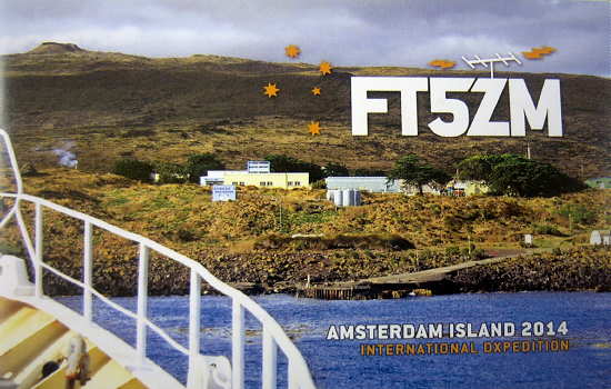
I've worked a number of island expeditions over the years on topband, but one of the rarest was in the mid-Indian Ocean, FT5ZM, on Amsterdam Island ... also right at sunrise.
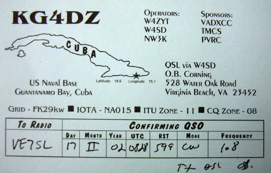
Another 'closer' island has always been a bit rare on 160, Guantanamo Bay, Cuba ... worked in mid- February, just after midnight.
In all of my years in the suburbs, I was never able to hear Europe on topband. It seemed that the noise-curtain surrounding my reasonably quiet location was still just too high for such 'over the pole' west coast treats. It wasn't until I moved to Mayne Island, off the SW coast of B.C., and re-installed my half-sloper, that the Europeans finally began to fill my log. Some nights, during solar-low years, the Europeans were workable before sunset ... on other nights, there were no signals other than Europeans, filling the band from 1800-1830, at times making the topband sound like 20m CW ... definitely not like the city.
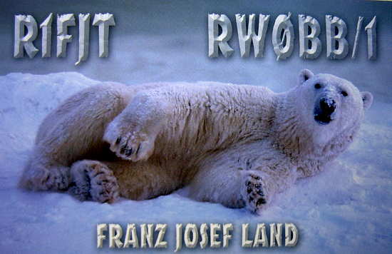
4Z1UF was worked in February, just after 8PM local time while R1FJT in Franz Josef Land was worked right at sunset in late October.

Africa is always tough on the low bands but the solar-low years of Cycle 23 brought some amazingly good conditions to the west coast. The two new ones, below, were both worked in November of '08 at around 10PM local time, right at sunrise in Africa.
Learning the quirks of topband propagation is still an ongoing project but over the years, 160m has been my favorite wintertime hangout. With T2GC on Tuvalu Island, worked last week, my present 160m DXCC total stands at 156 worked and 155 confirmed.
If you're looking for something different, some new fun... a bit of an operating challenge ... I know you'll find it on topband!
Steve McDonald, VE7SL, is a regular contributor to AmateurRadio.com and writes from British Columbia, Canada. Contact him at [email protected].
Our hobby – very diverse
There can be few hobbies that embrace so much as amateur radio. Some enjoy QRP, often making their own simple gear and each QSO is a thrill. Others spend a great deal of money on rigs, towers and antennas and enjoy just talking to others around the world. Some like the challenge of microwaves or optical. The list is endless.
We are lucky that our hobby can be enjoyed by all ages and abilities and in so many different ways. It is very easy to be critical of how others enjoy the hobby – I know as I am guilty of this! We should be thankful we are a “broad church” and allow each of us to enjoy the hobby in the way that suits us best. I used to enjoy building and field work, but because of my stroke I have had to adapt. Thankfully, I enjoy the hobby as much as ever.
Roger Lapthorn, G3XBM, is a regular contributor to AmateurRadio.com and writes from Cambridge, England.
Xiegu X108G Outdoor Version at JOTA 2015
Took the X108G Outdoor Version out to JOTA this weekend outdoors near Neys Provincial Park near Marathon, Ontario, temps during the day were 3c and at night was -4c first night and second night was -7c. We operated from a dining tent outside and was running battery power and a windom at about 15′.
We had light snow and rain during our outing and Saturday morning we did a hike to The Crack which is a large path through the rugged rock in the area.
http://superiorhiking.com/the-crack-in-the-rock/
Here are a few pictures of the weekend and a few links to YouTube videos of the X108G in action:


Was a great weekend out in the bush and having the 1st Thunder Scout Troop again take part in JOTA
Fred Lesnick, VE3FAL, is a regular contributor to AmateurRadio.com and writes from Thunder Bay Ontario, Canada. Contact him at [email protected].
 Ham Radio Deluxe |
 W5SWL Electronics |
 Ham Radio Prep |
 KB3IFH QSL Cards  Hip Ham Shirts  HamRadioAuctions HamRadioAuctions Reliance Antennas Reliance Antennas Enigma Shop Enigma Shop |  morseDX  Ni4L Antennas  R&L Electronics R&L Electronics antennas.us antennas.us QRV QRV |
- Matt W1MST, Managing Editor
