 |
 The Perception of Power
Power... or lack thereof
Richard Carpenter, AA4OO, is a regular contributor to AmateurRadio.com and writes from North Carolina, USA. Contact him at [email protected].
Where is the IC7300?
Today, through the post, I got my November 2015 copy of Practical Wireless. Suspiciously I could find no pictures or mention of the ICOM IC7300 transceiver in any advert at all. It is almost as if all the dealers have been told in no uncertain terms to sell the current products and, on pain of death, do not under any circumstances mention the IC7300. I am not saying this as fact, but it is all rather odd. A month ago everyone was full of the news and products were expected to ship by the year end. Perhaps ICOM have had second thoughts or were losing sales of current products?
There were plenty of adverts for the Yaesu FT991, although even the best published prices have since been bettered. No, I am very suspicious about why there is no mention of the IC7300. Just one dealer OK, this I could believe, but all of them tight-lipped???
ICOM what is behind this? Is there a story we are not being told?
Roger Lapthorn, G3XBM, is a regular contributor to AmateurRadio.com and writes from Cambridge, England.
Just good enough 10 MHz GPS reference
Some time ago I noticed that the Ublox Neo-7M GPS has a 10 MHz output which is locked to the GPS system’s accuracy. Most people kept saying how useless it was due to excessive jitter unless it was cleaned up with a phase locked loop of some sort.
At about the same time I installed the external reference input for my Elecraft K3. The K3EXREF enables the K3’s frequency to be locked to an external 10 MHz reference. What struck me was how its function is described:
- The frequency of the internal oscillator of about 49.38 MHz is continuously measured and averaged, obtaining a value to the nearest 1 Hz.
- The K3EXREF does not phase lock the K3’s reference oscillator and the external 10 MHz source has no impact on the K3’s phase noise performance.
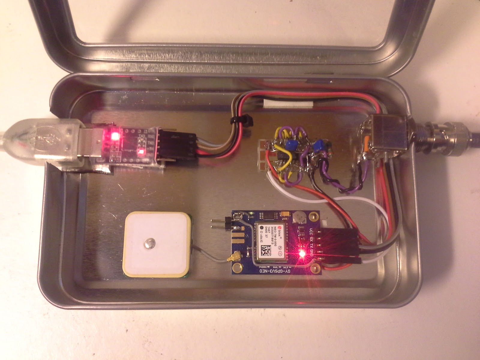
This got me wondering if the Neo-7M would be just good enough as a reference and that all the averaging internally to the K3 would take care of the jitter. I ordered one from Ebay for USD 12-13 together with an USB interface (USD 1.5) and hooked it up. (Actually the NEO-7M already has a built-in USB interface, but my board doesn’t support it). The result is shown above as assembled in a clear top tin. In my wooden house I can receive GPS indoors, so I have no need for an external antenna
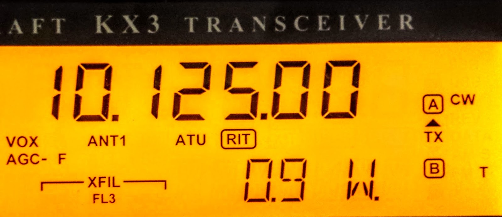
 The K3 accepts the input and I see the star in REF*CAL blinking. Just after turn-on of the K3 my 49.38 MHz reference frequency ends in …682 and after 10-15 minutes it has fallen and stabilized to …648, i.e. 34 Hz down in frequency. This is just 8 Hz off the reference value I determined manually was the right one when my K3 was new in 2009 (49.379.640).
All this taken together indicates to me that the K3 finds this 10 MHz acceptable for locking. The measurement to the nearest Hz, implies a measurement time of the order of 1 second and that seems to be enough to smooth out the jitter from the Neo-7M.
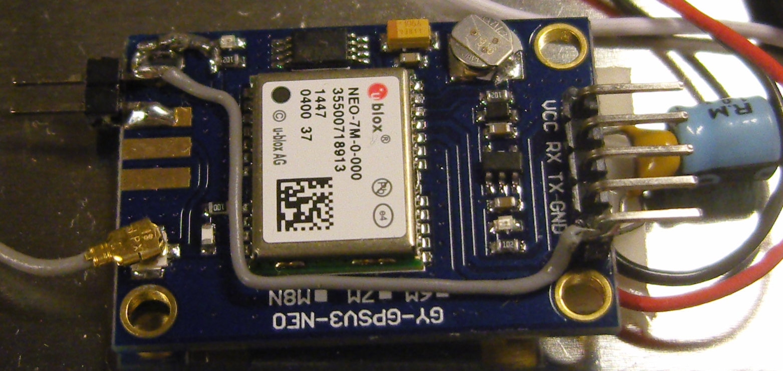
In order to get this to work I had to do some modifications to the GPS unit. First I had to get access to the timepulse on the chip’s pin 3. My connection is inspired by that of G4ZFQ and consists of a small wire from the left-hand side of the 1k resistor to the upper left hole. From there another grey wire goes below the chip and to the 5-pin header which is soldered to the Vcc, Rx, Tx, Gnd pins. The 5th pin is cut off and is just attached to the other pins through the plastic hardware.
The second modification was required in order to get it to run from the somewhat noisy USB 5 Volt supply. That took some decoupling between the Vcc and Gnd pins (220 uF and 0.1 uF in parallel), visible to the right in the image above, using good engineering practice to keep the wires as short as possible.
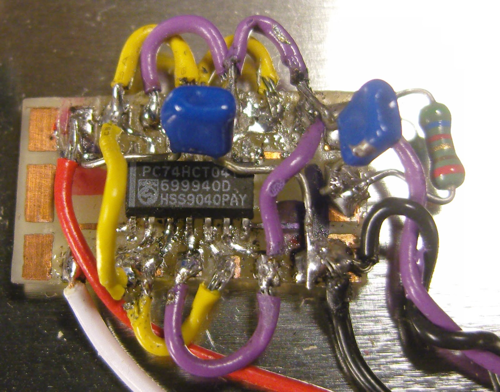 The timepulse is a 3.3 Vp-p output which cannot drive anything below 400-500 ohms impedance. Therefore I added a 74HCT04 driver that I have assembled on a little homemade SMD to DIL adapter PCB (easy to find on Ebay). It serves as a driver to feed the 10 MHz to the 50 ohm input of the K3EXREF.
The HCT04 IC has 6 inverters. One of them takes the input signal from the Timepulse output of the GPS IC and buffers it to drive the 5 other inverters in parallel. This is shown in the schematics at the end of this blog post.
The 5Vp-p output from the buffers is fed via 56 ohms to a connector that goes to the K3EXREF input. This is in accordance with the K3EXREF manual which says: “The 10 MHz source should have a signal level between +4 dBm and +16 dBm, nominal. For square wave sources, 2VDC to 3.3VDC peak is optimum. If the source is a 5V logic level, use a 50-ohm resistor in series with the input.“
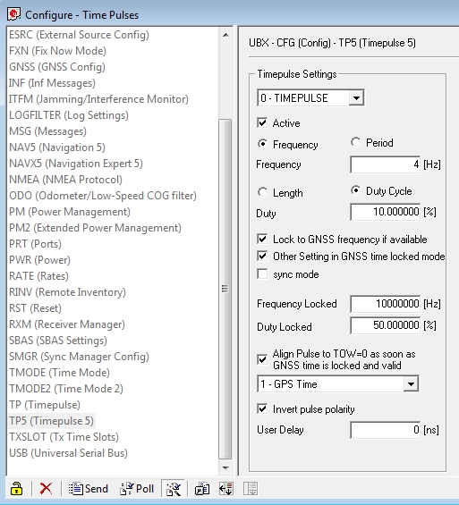 In order to set up the GPS I have used the u-center program (Menu: View, Configuration View, TP5 (Timepulse 5)) from Ublox and set it up with the parameters shown to the right. It blinks at 4 Hz before the signal is acquired and then switches to 10 MHz. This can be observed on the green LED connected to the Timepulse output also as it switches from blinking to a half-lit status.
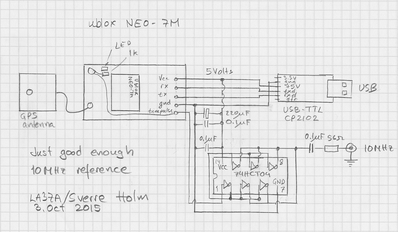
See also
Sverre Holm, LA3ZA, is a regular contributor to AmateurRadio.com and writes from Norway. Contact him at [email protected].
Just good enough 10 MHz reference
Some time ago I noticed that the Ublox Neo-7M GPS has a 10 MHz output which was locked to the GPS system’s accuracy. Most people kept saying how much jitter it had and how useless it was unless it was cleaned up with a phase locked loop of some sort.
At the same time I got the 10 MHz reference input for my Elecraft K3 (K3EXREF). What struck me was how its function was described:
- The frequency of the internal oscillator of about 49.38 MHz oscillator would be continuously measured and averaged, obtaining a value to the nearest 1 Hz.
- The K3EXREF does not phase lock the K3’s reference oscillator and the external 10 MHz source has no impact on the K3’s phase noise performance.
This got me wondering if the Neo-7M would be just good enough as a reference and that all the averaging internally to the K3 would take care of its jitter.I ordered one from Ebay for USD 12-13 together with an USB interface (USD 1.5) and hooked it up. The result is shown above as assembled in a clear top tin. In my shack I can receive GPS indoors, so I have no need for an external antenna
The K3 accepts the input and I see the star in REF*CAL blinking. Just after turn-on of the K3 my reference frequency ends in … 682 and after 10-15 minutes it has fallen and stabilized to …648, i.e. 34 Hz down in frequency. This is just 8 Hz off the reference value I determined manually was the right one when my K3 was new in 2009 (49,379,640).
All this taken together indicates to me that the K3 finds this 10 MHz acceptable for locking.
In order to get this to work I had to do some modifications to the GPS unit. First I had to get access to the timepulse on the chip’s pin 3. My connection is inspired by that of G4ZFQ and consists of a small wire to the upper left hole. From there another grey wire goes below the chip and to the 5-pin header which is soldered to the Vcc, Rx, Tx, Gnd pins. The 5th pin is cut off and is just attached to the other pins through the plastic hardware.
The second modification was required in order to get it to run from the somewhat noisy USB 5 Volt supply. That took some decoupling between the Vcc and Gnd pins (220 uF and 0.1 uF in parallel), visible to the right in the image above, using good engineering practice to keep the wires as short as possible.
The timepulse is a 3.3 Vp-p output which cannot drive anything below 4-500 ohms impedance. Therefore I added a 74HCT04 driver that I have assembled on a little homemade SMD to DIL adapter PCB. It serves as a driver to feed the 10 MHz to the 50 ohm input of the K3EXREF.
The HCT04 IC has 6 inverters. One of them takes the input signal from the timepulse output of the GPS IC and buffers it to drive the 5 other inverters in parallel. This is shown in the schematics at the end of this blog post.
The 5Vp-p output from the buffers is fed via 56 ohms to a connector that goes to the K3EXREF input. This is in accordance with the K3EXREF manual which says: “The 10 MHz source should have a signal level between +4 dBm and +16 dBm, nominal. For square wave sources, 2VDC to 3.3VDC peak is optimum. If the source is a 5V logic level, use a 50-ohm resistor in series with the input.“
In order to set up the GPS I have used the u-center program (Menu: View, Configuration View, TP5 (Timepulse 5)) from Ublox and set it up with the parameters shown to the right. It blinks at 4 Hz before the signal is acquired and then switches to 10 MHz. This can be observed on the green LED connected to the Timepulse output also as it switches from blinking to a half-lit status. Sverre Holm, LA3ZA, is a regular contributor to AmateurRadio.com and writes from Norway. Contact him at [email protected].
Surface mount soldering
If, like me, you have had an irrational fear of surface mount devices for some time, you will be glad to know its not as bad as you may think. I recently started working with SMD and while I suffer from shaky hands and have poor eyesight, its actually quite a methodical process and not as fiddly as you would think.
I created a 2 part video on SMD soldering using a hot air (reflow) station and using solder paste. In this video I created a QRP dummy load which is a great introduction into Surface Mount Components and at a great price of £5.95 available from Kanga Products
Dan Trudgian, MØTGN, is a regular contributor to AmateurRadio.com and writes from Wiltshire, England. He's a radio nut, IT guru, general good guy and an all round good egg. Contact him him here.
What’s Wrong With the ARRL?
Every so often a blog posting takes on the topic of “the ARRL needs to change.” A recent one came from Dan KB6NU, referencing some worthwhile ideas he has encountered via Rotary International. (I like Dan’s blog and read it fairly consistently.) Whenever I see this kind of article, my brain immediately thinks:
The ARRL is the worst US national amateur radio organization, except when compared to all others.
Yeah, its easy to criticize the ARRL, but it is the only game in town in terms of a national organization. And they do a lot of good for amateur radio and probably don’t get sufficient credit for that. (I should point out that Dan is very clear that he just wants to see the ARRL improve, especially in attracting new hams. I believe him and I share that motivation.)
It is hard being the ARRL.
Amateur radio is not really one hobby, it is a collection of hobbies and activities. We’ve got CW-enthusiasts, QRP folks, Emcomm volunteers, HF contesters, VHF contesters, tinkerers, 75m AM operators, repeater operators and on and on and on. Because the ARRL is a member-driven organization, it tries to balance these competing interests. Just listen to the random-vector criticism that spews forth: the ARRL is too focused on QRP, doesn’t do enough for QRP, only cares about HF, doesn’t do enough for HF, is against new digital modes, is always promoting new digital modes, thinks CW is the only way to go, gave us the No Code license, hung on to the Morse Code requirement too long. This list goes on and on. It really is impossible to keep everyone happy.
Like every large organization that I belong to, the ARRL is not perfect. But the good it does clearly outweighs the stuff I don’t like, so I enthusiastically support it. Said another way, I get enough benefit out of the membership to justify the dues. The key benefits for me are: QST magazine, Logbook of the World, contests, awards and representation with the FCC. QST is clearly the biggest benefit of membership and many people just view the membership fee as a magazine subscription.
A huge threat to an organization with such a print franchise is the shift from print to new media (video, web, blogs, podcasts, social). The ARRL web site has a lot of good information and most of the bugs have been worked out of the major redesign of a few years ago. They have a basic presence on twitter and podcasts. The ARRL has a youtube channel but the content is weak. At the same time, other people are putting out some good video content. Look at what HamNation, HamRadioNow, HamRadioSchool.com are doing.
The ARRL is a long-lived institution and like most long-lived institutions they tend to be grounded in the past and are a bit old school in nature. Attracting newly licensed radio amateurs, especially Techs, is the big challenge for the ARRL. I don’t know what market research the ARRL does but I suggest they establish on on-going program that gets inside the heads of newer licensees and potential hams to understand how they view the ARRL. This requires an ongoing investment that is coupled to strategy. I’ve seen marketing pros do focus groups, interviews, surveys, etc. that bring customer needs to the surface so an organization can respond to changes that attract new customers members.
If you are an ARRL member, what can you do to change things? Your avenue to make your views known is via your Division Director, so I suggest you reach out to him or her. (Contact information is listed in the front of every QST.) Don’t be surprised if your voice is mixed in with a whole bunch of other people’s views…kind of like Congress 
If you are not a member and spend a substantial amount of time having fun messing around with radios, I encourage you to join the ARRL. You might like it.
That’s my view, what’s yours?
73, Bob K0NR
The post What’s Wrong With the ARRL? appeared first on The KØNR Radio Site.
Bob Witte, KØNR, is a regular contributor to AmateurRadio.com and writes from Colorado, USA. Contact him at [email protected].
 Ham Radio Deluxe |
 W5SWL Electronics |
 Ham Radio Prep |
 KB3IFH QSL Cards  Hip Ham Shirts  HamRadioAuctions HamRadioAuctions Reliance Antennas Reliance Antennas Enigma Shop Enigma Shop |  morseDX  Ni4L Antennas  R&L Electronics R&L Electronics antennas.us antennas.us QRV QRV |
- Matt W1MST, Managing Editor
