 |
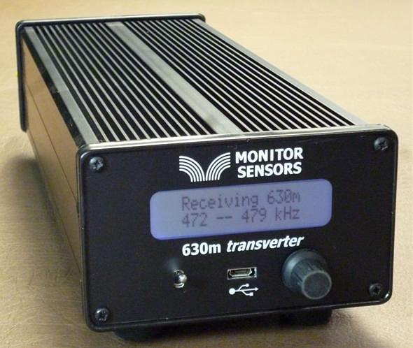
 The New VK4YB 630m Transverter
Now that beta testing is complete, production units are now ready for distribution from Monitor Sensors, a family environmental-sensor manufacturing company of which Roger is Governing Director.
The introduction of the VK4YB 630m Transverter presents another new option for those wishing to get on the band, or in the case of American amateurs, to get prepared for the band ... soon expected to be implemented in the U.S.
When I first started using the test unit provided, I was immediately impressed with how simple it was to set up and to get operational. It sits inconspicuously beside the main station's transceiver, taking up less space than the typical station speaker unit.
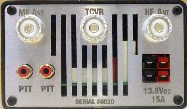
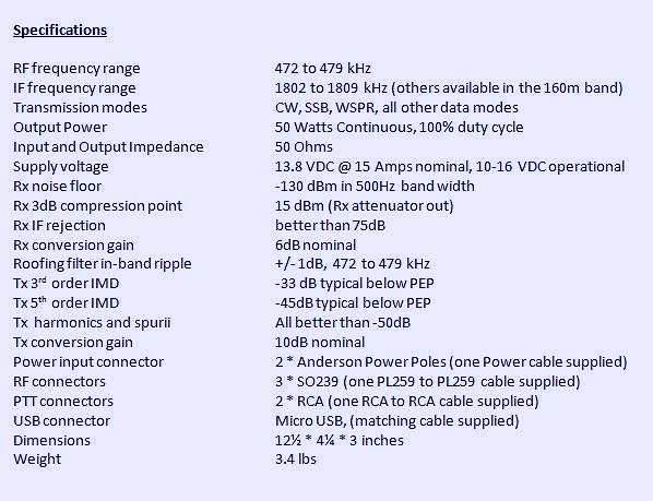
One usually associates 'transverter' operation with a rat's-nest of cabling or re-cabling to accommodate the new addition. The transverter arrived with all necessary cabling, even a nice Anderson power pole connector to connect the user-supplied 12V power source. A second pair of 12V contacts is also available for sharing with other station needs. One feature that I quickly appreciated was the dual RCA jack on the rear panel for controlling the transverter's PTT keying line. With my transceiver's PTT line already being used for another purpose, it was simply a matter of plugging-in (cable supplied) and sharing the line with the second jack ... no need for unplugging or using an external adapter to split the PTT line. Switching from 630m to normal HF operation is simply a matter of turning the transverter 'off' ... all HF operations are back to normal with antenna routing taken care of. There appears to be a lot of thoughtful engineering packed into this little box.
A look under the hood shows a well-planned and efficient use of space as seen in this pre-production prototype shown below. If Collins Radio were to manufacture a 630m transverter for the military, I can't imagine it being any better than this!
| prototype board under test |
"... we carefully match the FETs into three pairs. Each pair is matched to its opposite number but the pairs are chosen so 2 have low gain, 2 have mid gain and 2 have high gain. This improves the IPs and also the harmonics. With matched FETs we are getting the 2nd harmonic at typically -60dB. That's 10dB better than the stringent FCC requirement."
Roger's unit is running at 16 volts and produces 90W output, with his 630m WSPR signal being the one most often heard in North America from down under.
The transverter's multi-colored screen combines with a multi-function menu, allowing a visual on-screen display of numerous parameters such as RF output power, DC supply voltage and current draw, SWR, exciter drive power, heatsink temperature, graphic SWR display and various warning screens.
The transverter requires 3-5 watts of 160m drive from the station transceiver for full output power. Built-in safety circuits prevent overdrive from causing any damage. Similarly, transmitting into a high SWR or with no antenna connected is no cause for concern. Temperature sensors will trigger shutdown should the heatsink rise above 100 degrees C. Software also prevents out-of-band transmission.
This is a microprocessor controlled linear-transverter. This means that operating system software can be readily updated (via the supplied micro USB cable) as new features are implemented. It also means that any mode your transceiver is capable of operating on can be produced on 630m. At present, the most popular modes on the band are WSPR, CW and JT9 but I suspect this order may change once the band is opened up in the U.S.
A shortened eight-page Operator's Manual can be downloaded from the Monitor Sensors web site but units will ship with a more comprehensive 22-page manual. For more information regarding pricing and shipping, please contact Monitor Sensors here. For technical questions, please contact Roger here.
Steve McDonald, VE7SL, is a regular contributor to AmateurRadio.com and writes from British Columbia, Canada. Contact him at [email protected].
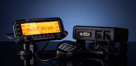
Review – BTech UV-50X3 (Tri-Band)
by John ‘Miklor’
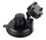
Included with the radio are: 50X3 Weight: Main Chassis 2.1kg (4.6 lbs) Specifications The 50X3 is FCC Part 90 certified for commercial use in the US. Control Head The suction mount is about the best I’ve ever used. It requires a smooth metal or glass surface, but the silicon rubber cup will not let loose. My control head has been mounted atop my computer for over a month, and it is going nowhere. The button functions are displayed on the LCD screen for easy function identification. The PTT button on the upper right is for Momentary or Toggle PTT. One press turns the TX on, next press turns it off. Setting to Toggle is convenient if running a net or using a mobile headset. 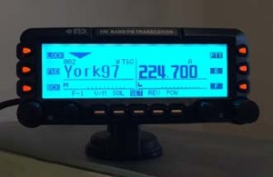 Cooling The 220 ham band transmit range is limited to 222-225MHz. The receiver is capable of being programmed above and below those frequencies, but may be outside of the performance range due to the ham band specific filtering.
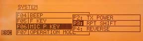
Microphone The radio comes with a full function keypad style microphone. On the right side are two slide switches that control the Lock and Lamp feature, and on top of the microphone are two frequency Up and Down buttons. Along with a 16 button DTMF style keypad are 4 programmable function keys. Choices are Squelch Off, TX Power, Rptr Shift, Reverse, and Tone Call. There are two microphone input jacks. One on the control head, the other on the main unit. There is also a built in microphone element inside the control head. Although the audio quality is excellent, the sensitivity is that of a standard microphone. The OTA reports were excellent with plenty of audio, so there’s no reason to shout. A nice feature in the audio section is an adjustable microphone gain control. There are 5 settings available. Min, Low, Normal, High, and Max. Normal is great for speaking in a normal volume an inch from the microphone. Running a net with VOX and a headset, you can bring it up a bit. Driving in an off road vehicle, you just might need to set it back.
Receiver Along with the standard VHF / 220 / UHF frequencies, the receiver covers: 0.5-1.7 MHz (AM Radio) The control head has built in speakers, as well as one in the main module. An external speaker jack in the rear also allows for a larger speaker if desired. The jack provides for either mono or stereo output. (each receiver can have it’s own speaker). I found a menu setting to adjust the tone of the speaker as well. Although there is more than ample audio output, when the volume control is all the way down, the radio is silent, as it should be. Cross Band Repeat The radio takes full advantage of the independent receiver by including a Cross Band Repeat function. I entered the VHF and UHF frequencies, power level and tones, selected the Cross Band mode, and was ready to go. The audio levels are preset and the audio quality reports were excellent. Cross band repeating using a 220MHz frequency was not possible. This is more than likely a precaution due to the minimal frequency separation. Display The control head has a large 5″ LCD with your choice of background colors. Options include White-Blue, Sky-Blue, Marine-Blue, Green, Yellow-Green, Orange, Amber, and White. The brightness and contrast are also menu selectable.
Unless you are only entering a few channels, I would recommend the optional PC05 programming cable. The UV-50X3 uses the CHIRP programming software. Scanning in the VFO mode allowed me to scan either the VHF, 220MHz, or UHF band. In the Channel mode, the scan would select any channel in the list regardless of band. Power Cable There are radios that draw less power whose power cables use thinner wire, lower value fuses, and can be plugged into accessory plugs. Do NOT use these cables, even though they may be plug compatible. The 50X3 draws twice the current, and will blow the fuses and possibly overheat the wire. The cable on the 50X3 appears to match that of the hi-power Yaesu, Icom, Kenwood series. ONLY use the proper cable for the radio. Base Station Operation For mobile drive testing, I teamed this radio with a Nagoya Tri-Band TB320A and SB-35 NMO mag mount and the results were excellent. Conclusion Some of the added advantages to the US market are the FCC Part 90 certification, local US support, and exclusive program support using CHIRP software. The radio can also be shipped worldwide by contacting BTech directly. This is definitely one of the nicest mobile transceivers I’ve used; and yes, I’ve owned the “big 3”.
More Information: Miklor.com |
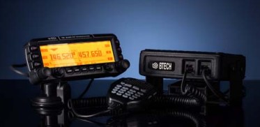
 Four years after its initial design, the VGC 6600PRO has evolved into the BTech UV-50X3, a full featured Tri-Band mobile that delivers a full 50W on VHF and UHF, with addition of a 220 MHz module that delivers 5W output. The 220 MHz module was specifically designed and filtered for 222-225MHz US ham band operation. I mention this as there are currently radios being advertised as Tri-Band operating in the range of 240-260MHz that are not adaptable to frequencies below 240MHz due to their internal filtering.


Hans, PD0AC, is a regular contributor to AmateurRadio.com and writes from Almere, The Netherlands. Contact him at [email protected].
USB Ports: Gray, Blue, Yellow, or Red?
Did you know that the different colored USB ports on your computer aren’t just for decoration? That the colors actually mean something?
What? You’ve just been plugging USB cables into whichever port is most convenient? What a rookie mistake! 🙂
Well, some ports are a whole lot better than others, and some even do cool things that you probably didn’t know about.
Gray/Black USB Ports
 These are your run-of-the-mill USB 1.0/2.0 ports. They have throughput ranging from 1.5 Mbit/s to 480 Mbit/s in later versions.
Blue USB Ports
 These are newer USB 3.0 ports. They range from 5 Gbit/s (USB 3.0) to 10 Gbit/s (USB 3.1). These are the better choice for devices that require faster speeds.
Yellow (or Red) USB Ports
 These are called “sleep-and-charge” ports, meaning that they continue to supply power even when the computer is sleeping. This makes it convenient to charge a phone or tablet from your laptop battery.
Just as a side note, I’ve had computers that required me to enable this feature in settings before it would work.
Note: Most of the time white USB ports are USB 1.0, but some manufacturers use them for USB 3.0 ports.
So, next time you go to plug in a USB device that requires fast throughput, double check that you’re using the fastest port available on your computer!
Matt Thomas, W1MST, is the managing editor of AmateurRadio.com. Contact him at [email protected].
Activation Alert: WØC/FR-030 (Chief Mountain)–3569m / 11709ft
Date: 7 August 2016
Time: Approx. 1500 UTC – 1800 UTC
Region: CO-Front Range
Elevation: 3569 m / 11,709 ft – 6 Points
Call Sign: KDØBIK
Frequencies: 14.342.5-ssb, 18.157.5-ssb, 28.327.5-ssb, +/- 147.42-fm
Equipment: Elecraft KX3 / Buddipole versatee vertical & Yaesu VX-8 / Elk Log-Periodic Antenna
APRS Track: On Road / On Trail
Can you believe it? It’s been almost four years since my last Summits on the Air activation. I’ve really missed it. The last SOTA activation was a multi-activation of both Chief Mountain (yes, I’m repeating) and the nearby Squaw Mountain (WØC/PR-082).
Of course the really big news is not the fact that I’m doing my first SOTA activation in almost four years, it truly is the fact that this year is the 25th Annual Colorado 14er Radio Event. A few years ago the event was slightly modified to also include all the SOTA summits which of course are not always 14,000 foot summits.
While band conditions in recent days have been really poor, the fact my operating position will be almost 12,000 feet in altitude is of course encouraging me to go ahead and pack all my gear. So I do plan to setup for HF operations, but I will also spend more time (more time than usual) working hams on neighboring peaks on 2m and 70cm FM frequencies.
At the present time, 23 hams have posted their plans for operating over the two day weekend. I’m sure over the next 24-36 hours even more will post their intentions.
I’m really looking forward to combining my love of hiking, radio and even geocaching (there is a geocache on the summit of Chief). Please point your antennas towards Colorado this weekend. I hope to work you from the summit of Chief Mountain WØC/FR-030.
Until next time…
73 de KDØBIK (Jerry)
Jerry Taylor, KD0BIK, is a regular contributor to AmateurRadio.com and writes from Colorado, USA. He is the host of the Practical Amateur Radio Podcast. Contact him at [email protected].
Antenna tuning by stealth
One of the most important documents for anyone who wants to know what makes a magnetic loop tick is Leigh Turner VK5KLT’s “An Overview of the Underestimated Magnetic Loop HF Antenna” which can be found on his club website.
Midway through building my version of Loftur Jónasson – TF3LJ / VE2LJX‘s Automatic Loop Controller, I came across Leigh Turner’s impassioned plea to consider this noise bridge antenna tuning design mentioned on page 32 of the “Overview”. As a concluding note VK5KLT states that he considers “The perceived need for a slick and salubrious auto-controller for properly tuning an MLA is oftentimes overrated and exaggerated, IMHO”.
He argued that elaborate microcontroller aided automatic loop tuning circuits are unnecessary and people should consider using this more covert and considerate approach. I think the bridge could be an excellent idea and a simpler way of staying in tune as you change frequency for all sorts of antennas. For a magnetic loop, it still requires a way to remotely adjust the tuning capacitor.
“The circuit goes inline between the rig and the antenna and sends a gated broadband noise signal to the antenna using a directional coupler and a noise bridge. You just listen on the desired operating frequency and watch your RX S-meter for a sharp dip whilst adjusting the loop tuning capacitor.
You simply remotely tune the loop with the aid of the receiver S-meter while you are on the wanted frequency without keying up and TX power output. This makes tuning a breeze without having to move off frequency and have the TX put out any RF power.”
VK5KLT mentioned the MFJ-212 Matchmaker that uses this same approach (and which is still on the MFJ catalog at US$99.95) and also referenced ZL3KB’s April 2001 RadCom article (pp17-21) as an easy and more economical way to replicate the same functionality.
“The distinguishing merit of the novel gated coupler/noise bridge loop tuning method is it’s completely passive and covert in operation; you don’t transmit any TX power whatsoever to attain an optimal loop tune setting. The technique makes for fast, QRM free, safe and easy QSY shifts and netting a frequency.” Leigh Turner adds that it’s even simpler if you use a pan adaptor or a modern SDR receiver as you can see the sharp null on the screen of the band scope display.
Kelvin Barnsdale ZL3KB’s RadCom article describes building and using the wide band noise bridge as a silent antenna tuning indicator. These four pages include circuit, PCB design and layout and full details of BOM and balun/transformer construction.
On 14 May 2001 ZL3KB published a 4-page follow-up pdf document “Instructions for Antenna tuning Noise Bridge” with info supplementary to the RadCom article about construction and operation. This article has an updated circuit and parts layout and refers to an issue B of the PCB. The new board includes places for the LED and dropping resistor R14, and pads for the two 100Ω load resistors and the two diodes D2 & D3.

This is the updated circuit with some updated values.

This indicates parts placement with the updated PCB.
Here is the foil side of the updated PCB

I contacted Kelvin Barnsdale and was lucky enough to obtain the PCB above.
Ham College 19
More about Multi-mode transceivers and a few demonstrations.
1:03:27
George Thomas, W5JDX, is co-host of AmateurLogic.TV, an original amateur radio video program hosted by George Thomas (W5JDX), Tommy Martin (N5ZNO), Peter Berrett (VK3PB), and Emile Diodene (KE5QKR). Contact him at [email protected].
 Ham Radio Deluxe |
 W5SWL Electronics |
 Ham Radio Prep |
 KB3IFH QSL Cards  Hip Ham Shirts  HamRadioAuctions HamRadioAuctions Reliance Antennas Reliance Antennas Enigma Shop Enigma Shop |  morseDX  Ni4L Antennas  R&L Electronics R&L Electronics antennas.us antennas.us QRV QRV |
- Matt W1MST, Managing Editor
