New link HF Signals added

A new link for Ashhar Farhan's new BITX40 production website, HF signals added to the right hand side column of my blog. Sites that do it for me.


You can guess what I am going to write about next?


Steve, G1KQH, is a regular contributor to AmateurRadio.com and writes from England. Contact him at [email protected].

Boy am I rusty!!

The LZ CW contest was on this weekend and the exchange the DX stations have to give out are similar to the exchanges in the CQ WW DX CW contest which is on next weekend. This gave me the idea of sitting down at the rig on Saturday to see how my contest copy skills were coming along. The propagation was good, sunspots were not so great but the band was very busy with DX and North American stations. Before I started I had to be honest with myself that my contest practice times have been far and few. Two weeks ago I started my Morse Runner software program and went to the LWCO.net code practice site to get my ears back in tune with the CW contest music!! As the old saying goes "if you don't use it you loose it" I defiantly noticed that my contest copy speed is not the same as it was in the past. I have only myself to blame in that I have not been on the air both with QSO's, contests as well as practicing with the 2 above mentioned CW programs. Now instead of this experience getting me discouraged it has encouraged me to get back up in the saddle and move in a positive direction. But I did find that just a short time away I can get really rusty!

Mike Weir, VE9KK, is a regular contributor to AmateurRadio.com and writes from New Brunswick, Canada. Contact him at [email protected].

Smartlock

The Smartlock is an accessory for my SGC SG-239 HF Smartuner, and other ATUs they make. It can be bought ready made or built.

There are indicator LEDs that signal status (TND, l ‘Z’, 2:1, PHZ, FWD, Auto & Man) on the lower section of the PCB of the SG-239 but they are only visible near the unit. As they recommend mounting the unit in a weatherproof container and as close to the feed point as possible, it’s unlikely these will be useable except in testing and servicing.
For reference – here are the indicators and connections on the transceiver end of the SG-239:
B.I.T.E.* Status LED Descriptions – *Built In Test Equipment
TND This LED will light when the tuner has found an acceptable match. It will remain lit until conditions have changed which will cause the tuner to find a different match. (i.e. A new transmit frequency has been detected, or tuner has been reset.)
L ‘Z’ This LED shows the status of the antenna impedance. When lit, the impedance is 50 ohms or less. When off, the impedance is greater than 50 ohms.
2:1 This LED will light when the VSWR is greater than 2:1. It will extinguish when VSWR is less than 2:1.
PHZ This LED indicates the status of the antenna reactance. When lit, reactance is inductive. When off, reactance is capacitive.
FWD This LED indicates the presence or lack of RF power from the radio. When transmitting, the LED will light to indicate RF is being detected. In receive, the LED should be extinguished.
OTHER All LEDs will blink on and off at a rate of 2Hz to indicate the tuner was not able to find a valid match.
The LEDs are very small and quite faint and almost impossible to see on a sunny day.
As the ad below indicates the Smartlock provides two controls that can be used remotely from the tuner and close by the radio – allowing the operator to lock or stop the ATU constantly retuning as the load changes and to reset which forces a retune the next time a signal is transmitted.
The Smartlock also indicates if the ATU managed to tune the antenna, and if the lock is on. The lock can be invoked when the antenna is to be used for receive or when there are too frequent changes in the physical environment of the antenna such as when mobile and passing trucks or going under bridges….
Installation requires normal coax and a four conductor cable for power and control.
—-
SMARTLOCK, FOR SG-230/237/239 SMARTUNER
$60.00
Catalog #54-63
The SmartLock provides two external controls for the SG-230/237/239 Smartuner. The locking function prevents retuning despite changing antenna loads. The reset function forces the coupler into a retune cycle the next time a signal is transmitted. Tune and lock status is indicated by one green and one red blinking LED. Supplied with 9 feet (2.5 meter) connecting cable. For use with SG-230/237/239 couplers manufactured after July 1, 1993 only.
From the product number this seems to be the unit described above, on the SGC shop page at http://www.sgcworld.com/shopsite_sc/store/html/page5.html

This is the official circuit from the manual for the SG-239 (http://www.sgcworld.com/Publications/Manuals/239man.pdf)
Its simplicity and the cost of the assembled unit have inspired a number of people to roll their own.

The colour code of the cable to the Smartuner appears to be:
TND = Green,
HLD/RSET = White
+12V = Red
Gnd = Black

Simplified SmartLock
Phil Salas – AD5X – decided to remove the components making up the voltage regulator part of the circuit.
“I wanted to build a SmartLock to use with my SG-239. After studying the SmartLock schematic, I couldn’t figure out why SGC put in the transistor and zener diode. The ST-TNE input on the SG-239 is just a 1.5K resistor to an open collector transistor to ground. So I eliminated Q1, R3, D1 and C3 on the SGC SmartLock schematic. My final circuit is shown below. I used a DB9S connector to interface with the SGC tuner (I attached a DB9P to the tuner interface wires), and a PowerPole interface for 12VDC. This way I could use a standard DB9 extension cable as necessary for interfacing between the tuner and SmartLock. I used ultra-bright LEDs (3000mcd or so) to provide plenty of visibility.”
Phil Salas’s build of the Smartuner

There is another variation by Luca Molino IV3ZNK that can be seen at http://www.xluke.it/2016/07/28/smartlock-per-sgc-239
This uses a tiny PCB available on Italian eBay from a seller who wanted 50 € to send one to Australia!
I have worked out a way to use a scrap of veroboard to hold the two capacitors and one of the resistors and to manage the wiring between the base and the panel of the enclosure which is probably more efficient and certainly faster. As well I noticed that the PCB seems to be designed for a different kind of DPDT switch where the centre poles are not in the centre!?! So I can add the satisfaction of saving whatever Euros I would have ultimately paid to the greater satisfaction of having nutted out the layout of the veroboard scrap…
Luca used the simplified circuit by Hans Nussbaum DJ1UGA which appears to have in turn have some subsequent input from OE7OPJ (who by the way has a very interesting website at http://www.qth.at/oe7opj/).
This circuit can also be seen at http://www.qth.at/oe7opj/homemade-smartuner-lock.htm.
The components required are
2 x 1k5
2 x 100nF
Green LED
Red LED
DPDT switch
SPST MOM pushbutton
connectors
enclosure
Pretty neat!

text of the italian site:
L’accordatore automatico SGC-239 indubbiamente è un gran bello strumento. Si collega e funziona ottimamente con qualunque radio (HF) semplicemente utilizzando un cavo coassiale e una fonte d’alimentazione a 12 volts. Non è particolarmente esoso di corrente e anche in utilizzo SOTA non va a gravare sull’autonomia giornaliera. Ne ho trovato uno usato sui soliti canali nazionali ad un prezzo decente e non mi sono fatto scappare l’acquisto. Accorda davvero di tutto gestendo potenze da 1,5 a 200 watt. Ottimo per il mio Yaesu 817, ma altrettanto utile per le “normali” radio munite dei canonici 100 watt.  Per poterlo però utilizzare al meglio, si rende necessario l’acquisto di un interfaccia che permette di resettare o bloccare lo stato d’accordo del SGC-239. Tale interfaccia (SMARTLOCK) si trova però in vendita a quasi 100 euro, decisamente troppi per 2 condensatori, 2 resistenze, 2 led e un paio di interruttori. La prima idea è stata quella di prendere lo schema presente sul manuale dell’accordatore e realizzare su basetta forata il circuito. Cosa questa realizzabile, ma che avrebbe dato un idea di “precarietà” a tutta la realizzazione. La scelta a questo punto è ricaduta su un mini circuito stampato realizzato con maestria da Danilo Cramaglia (lo trovate su Ebay come utente Martelloman), che partendo dallo schema elettrico mi ha consegnato quanto riportato in foto:
The SGC-239 automatic tuner is undoubtedly a very nice tool. It connects and works well with any radio (HF) simply by using a coaxial cable, and a power source to 12 volts. It is not particularly power hungry and even practical to use on a routine SOTA outing. I found one used on the usual national channels at a decent price. It really suits around handling power output from 1.5 to 200 watts. Great for my Yaesu 817, but just as useful for “normal” radio equipped with 100 watt “cannons”. 
But in order to make the best use, it is necessary to obtan an interface that allows you to reset or block the status of the SGC-239. This interface (SMARTLOCK), however, is for sale at nearly 100 euro, far too much for 2 capacitors, 2 resistors, 2 LEDs and a pair of switches. The first idea was to use the circuit in the tuner’s manual and build it on perforated board. While this is feasible, it could give an idea of “insecurity” to the whole creation. Instead I chose a mini PCB made with skill by Danilo Cramaglia (Ebay-user Martelloman), which, starting from the wiring diagram handed me what is reported in the picture:

I plan to use this wiring arrangement for the 4 pin plugs, socket and line.
1 Red – +12V
2 Green – Tuned
3 White – Hold
4 Black – Ground and -12V

As well Philip Storr VK5SRP describes his version at http://www.philipstorr.id.au/radio/seven/accessories.htm.

SGC Smartlock control

In the hand book to the SGC SG237 Auto Antenna Tuner there is a circuit for an interface they call the SmartLock and it allows some manual control over the AATU and more importantly, it indicates when the tuner has tuned successfully.
—–
JH2CLV has documented his build.
These photos (from http://www5a.biglobe.ne.jp/~jh2clv/newsmartlockmaking.htm) give an idea of the layout which uses an external “chocolate block” connector for the 4 core power and control cable.
Case used is a plastic case – HA1593-KB of TAKACHI.
The main parts are as follows.
① DC-JACK
② 4P harmonica terminal (Chocolate block)
③ 6P toggle SW – actually a DPDT switch
④ push button SW
⑤ LEDs (red and green)
⑥ resistance (150Omu-330Omu)
⑦ capacitor (optional)
⑧ 9V3 terminal Reg (7809)
⑨ plastic case (TAKACHI / HA1593-KB)
⑩ wiring material
——-
Also http://www5a.biglobe.ne.jp/~jh2clv/smartlockmaking.htm has details of changes – design and layout…
(2) inside the box configuration
The shielded 4 core wire is clamped in the cable tie through a pull through bushing. The case uses a diecast aluminum box TD 5-8-3B (55x30x80) by TAKACHI. The front of the enclosure has the Normal / Lock switch (2-pole, double-throw), the Tuned LED (Green), the Locked LED (Red) and the Reset switch (Make contact). It includes the three-terminal regulator. The bypass capacitors on the circuit diagram are omitted here.
(3) box overview and operation
Once tuning is complete the Tuned LED (Green) glows. If the Normal / Lock switch is pointing to the right, the Lock side, the Lock LED (Red) is lit and fluctuating SWR, etc. does not cause automatic re-tuning.
If the switch is set to the Normal side, normal operating conditions prevail, the SG-239 will automatically start tuning if SWR or the band is changed.
If you press the RESET (red) button, the ATU will re-tune.
—-
Also check http://g3ynh.info/atu/sgc230.html for detailed description of using the Smartuner with a balanced antenna.

For some good ideas about how to protect the SG-239 see http://dg6hd.darc.de/html/sgc-239.html. He uses a large-ish electrical junction box and includes windings on toroids…

So here is my effort successfully completed today…
I used the simplified circuit by Hans Nussbaum DJ1UGA and the front panel layout of Phil Salas AD5X. I managed to squeeze everything into a compact package – a small die cast aluminium enclosure 64 x 58 x 35mm which Jaycar sell for $9.95. And that was the main cost. Everything else was on hand.
I’ve yet to label the panel, but the green LED indicates a successful tune, the red LED is on when the switch is in the Locked position, and the push button switch is the reset. I used 4 pin sockets and line plugs to connect to and power the Smartuner. And I used a DC socket to supply 12V power. I had planned to use power poles but decided that would not fit comfortably in this small enclosure.
The ATU is housed in a plastic lunchbox which can be protected by a larger rubber waste paper bin as recommended in the SGC manual.


Amateur Radio Weekly – Issue 134

Hara Arena items to be auctioned off starting Thanksgiving
The auction will include a limited number of Hara Arena and Cincinnati’s Crosley Field seats, Hara signage, photos, posters, sports and event memorabilia, sports equipment, chandeliers, catering items, tables and chairs.
Dayton Daily News

Simulating JT modes: how low can they get?
In this post I’ll show how one can use the signal generation tools in WSJT-X to do decoding simulations.
Daniel Estévez

Does QRP Really Work?
I have heard the saying so often “Life is Too Short for QRP”. For some reason, many radio amateurs refuse to embrace and even eschew low power.
NY4G

Hams on Strava
Many DXers and Contesters also participate in endurance sports such as running, cycling, and triathlon when not on the radio.
AmateurRadio.com

The Doctor is in: Stealth Antennas
Sometimes the best antenna is the “least” antenna.
ARRL

Amateur radio installation in a 2016 Ford F-150 SuperCrew
Installing in a truck and an evolving digital radiosphere presented some challenges.
Kevin Sanders

Ham Radio 360: ARES; an Introduction
Ham Radio 360 talks to Cecil Higgins (AC0HA) the ARES Section Manager for Missouri.
Ham Radio 360

Field Results for an AS-2259/GS Antenna
Let’s start with the good news first. The antenna worked like a champ. From suburban Chicago, our first contact was Toronto.
N4AE

Video

DEF CON 24: I Amateur Radio And So Can You
Kat Sweet explains how Ham Radio can be incorporated into everyday hacking.
K7FTW

Yaesu FT-817 QRP through a mag mounted Ham Stick
I make a QSO while testing out a 40 meter ham stick in a mag mount configuration.
KD9EAS

Ham Radio 2.0: Unboxing and testing the Yaesu FT-891
Yaesu’s newest HF mobile radio has some cool new features, but leaves out other options.
Ham Radio 2.0

ARRL Webinar: CHIRP Programming
This ARRL webinar offers a brief overview of the free, open-source CHIRP software, which can be used to program most radios.
ARRL

Ham shack kitten
Essex Ham’s Shack Kitten, Splodge, gets his own YouTube video.
Essex Ham


Amateur Radio Weekly is curated by Cale Mooth K4HCK. Sign up free to receive ham radio's most relevant news, projects, technology and events by e-mail each week at http://www.hamweekly.com.

More On The PAØRDT E-Probe

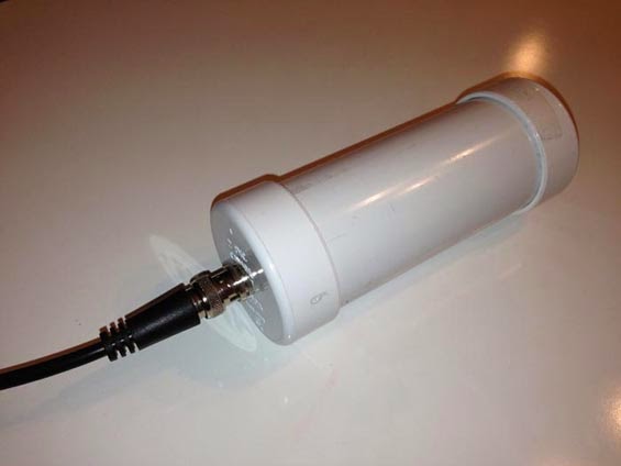
Courtesy: http://www.leeszuba.com/projects/


Another recent reflector question about noise mitigation for active e-probe antennas brought further incite from Roelof Bakker, PAØRDT.


I found particular interest in his method of determining if the noise is being picked up by the antenna or being introduced by the feedline. As well, Roelof suggests one of the most important aspects of homebrewing ... keeping detailed notes of all tests or changes. He also suggests maintaining a healthy outlook regarding noise and rather than getting discouraged, take on the challenge of overcoming it!

Hello all,

I have been dealing with this subject for more then 10 years now and
I am pleased to pass on what I did learn so far.

The first item to look at is noise pick up on the feed line. This
can be a coax cable or a CAT5/6/7 network cable. Looking for noise
pick up on the feed line should be done without the active antenna
connected. Otherwise everything should be the same as when using the
antenna.

Ideally the antenna should be replaced by a 50 ohm termination that
can handle the power that is supplied by the DC-power supply feeding
the antenna. However, this is not necessary to achieve good results.

I am fortunate to own a PERSEUS SDR, that besides an excellent
receiver is also a nice piece of test gear. For noise pick-up
measurements I use HF-Span that changes the PERSEUS into a 0-40 MHz
spectrum analyser with a noise floor of -112 dBm. For narrow band
measurements the PERSEUS is used with Linrad, which can provide
accurate results.

Whilst looking at noise pick-up on the cable, one can unplug all
suspect devices and check if the noise is still present.

The most effective measure is grounding the shield of the coax cable
at the bottom of the mast, but I had still noise ingress of about -
100 dBm around 15 MHz. This could be solved by moving the power
supply and interface of the antenna from the operating position to
the location of the cable entry to the house. This minimises the
length of cable inside the house before the a rf-isolating
transformer used in the interface.

It is mandatory to use a separate radio earth, isolated from the
mains earth. My PC is connected to a mains outlet with a mains earth
connection, but no other equipment in the shack is using the mains
earth. This works for me.

There is also a discussion about the use of a common mode choke
versus a rf-isolating transformer. I have tried both and they both
work. However a rf-isolating transformer is much easier (and
cheaper) to build than common mode chokes with a winding of coax
cable.

In this regard, I should mention a source of interference that is
easily overlooked: receivers. It is not uncommon to own more than
one receiver and it appears that the antenna port is often far from
clean. I am using four SDR's which are fed from a balanced Norton
amplifier / four port splitter and these produce noticeable noise.
Using four rf-isolating transformers at the outputs of the splitter
eliminated the noise. My mini-whip is feeding up to 8 receivers
(hardware) via amplifiers /splitters / rf-isolating transformers
without degrading the receiver noise floor by mutual noise ingress.

The last point is about masts. A metal mast will decrease the signal
level when the antenna is mounted close to it. A short PVC extension
mast will help. The reason I am using a non-conductive mast is a
practical one as cheap and sturdy stackable camouflage net mast
sections were and are still available in western Europe. These are
ideal for either testing antennas and for permanent installations.
Metal masts can introduce problems by being resonant at a certain
frequency and receiving noise that can be transferred to the feed
line. However, checking the feed-line as described above will make
clear if this is the case or not. If there are no problems, there is
nothing against the use of a metal mast.

As every location is different, it is no use to provide an exact
recipe to solve noise problems. I believe that a systematic approach
is mandatory; take notes etc. as it is too easy to run in circles.
By all means do measure what you are doing, otherwise you will walk
in the dark for sure.

The good news is that it is still possible to build a low noise
reception system in the city and doing so can be fun! What might
also help is to change the attitude from 'it should not be there
after all' to 'what can I do about it!'

Best regards and 73,
Roelof Bakker, pa0rdt

If you're thinking about having a listen on LF or on 630m, the e-probe antenna can be a very effective solution .... and it takes up very little space. The finer details regarding the PAØRDT active antenna may be found here and here. All previous blog postings related to this topic may be found here.

Steve McDonald, VE7SL, is a regular contributor to AmateurRadio.com and writes from British Columbia, Canada. Contact him at [email protected].

Subscribe FREE to AmateurRadio.com's
Amateur Radio Newsletter

 
We never share your e-mail address.


Do you like to write?
Interesting project to share?
Helpful tips and ideas for other hams?

Submit an article and we will review it for publication on AmateurRadio.com!

Have a ham radio product or service?
Consider advertising on our site.

Are you a reporter covering ham radio?
Find ham radio experts for your story.

How to Set Up a Ham Radio Blog
Get started in less than 15 minutes!


  • Matt W1MST, Managing Editor