 |
 LF / MF News From Monitor Sensors

A note from Roger, VK4YB of Monitor Sensors, reports some interesting news.
You might recall that his company manufactures a very versatile and well-engineered 630m transverter which was used at both ends of our two 630m JT9 contacts last year during the fall equinox propagation peak between North America and down-under.
Roger now reports that Monitor Sensors will be producing a new 2200m transverter, with all of the bells and whistles found on the 630m unit which has proven to be a real workhorse.
Monitor Sensors 2200m Transverter
The Monitor Sensors TVTR2 2200m Transverter enables any Amateur Radio Station, equipped with a conventional HF transceiver, immediate, all mode, access to the new 135.7-137.8 kHz, 2200m band.
The receiver design incorporates a 7pole Chebyshev filter, 3kHz wide roofing filter and a 5 pole Chebyshev filter in cascade before the double balanced, commutating mixer, fed by an ultra stable, temperature compensated, extremely low phase noise, MEMS local oscillator. The mixer is followed by a Chebychev band pass filter into an ultra linear, low noise, current feedback, IF amplifier. The receiver noise floor, in a 500Hz bandwidth, is -125 dBm and yet the onset of compression is not reached until +11dBm. A front end 20dB attenuator can be switched in for even higher signal handling. Overall receiver gain is set to +6dB, or -14dBm with attenuator in.
The transmitter input circuit incorporates a 0-14 dB switched step attenuator to prevent over driving. The same mixer and local oscillator are used on the transmit side. The PA uses 6 rugged lateral FETs in class AB push-pull to easily achieve the 50 watts rated output. Lateral FETs are inherently linear and thermally stable. The transmitter can be run at full power, indefinitely, into a dead short or open circuit without any danger of damaging the FETs. Transmit-receive switching is automatic with user selectable VOX delay. Alternatively the PTT line may be used.
The transverter employs extensive and accurate metering. Power input and output, SWR, Frequency, Attenuation in use, Temperature, Supply Voltage, Current and Resistance are displayed.
Transmission is inhibited if carrier frequencies outside the 135.7-137.8 kHz band are detected. A tuning screen may be selected which displays SWR in digital and graphical form for easy antenna adjustment. The menu system is self explanatory and users report no manual is needed, although one is supplied. A USB socket is provided for future code upgrades (free of charge) from the Monitor Sensors web site.
The transverter has been designed for the best possible protection against accidental mishaps. It will survive reverse polarity supply and the injection of 100 watts of HF into any of its ports whether in transmit or receive mode. If supply current exceeds 25 Amps, the supply is cut in 3 microseconds. This electronic breaker can be reset by simply switching off and on again. The transmitter will shut down in the unlikely event that the internal heat sink reaches 90°C. The cooling fan is under the proportional control of the microcomputer and begins operation above 35°C. Any unusual operation will cause the screen to turn red and an appropriate warning will be displayed.
TVTR2 Specifications
RF frequency range 135.7 to 137.8 kHz
IF frequency range 1805.7 to 1807.8 kHz (others available in the 160m band)
Transmission modes CW, SSB, WSPR, and all other data modes
Output Power 50 Watts Continuous, 100% duty cycle @13.8V supply
Input and Output Impedance 50 Ohms
Supply voltage 13.8 VDC @ 15 Amps nominal, 10-16 VDC operational
Rx noise floor -125 dBm (500 Hz bandwidth)
Rx 3dB compression point +15 dBm (Rx attenuator out)
Rx IF rejection better than 75dB
Rx conversion gain +6dB nominal
Roofing filter in-band ripple +/- 0.5dB
Tx 3rd order IMD -33 dB below PEP, typical at 50W output
Tx 5th order IMD -45dB below PEP, typical at 50W output
Tx harmonics and spurii All better than -50dB
Tx conversion gain +10dB nominal
Power input connector 2 * Anderson Power Poles (one Power cable supplied)
RF connectors 3 * SO239 (one PL259 to PL259 cable supplied)
PTT connectors 2 * RCA (one RCA to RCA cable supplied)
USB connector Micro B USB, (matching cable supplied)
Dimensions 12½ * 4¼ * 3 inches, 320 * 120 * 76 mm
Weight 3.4 lbs, 1.6 kg
In addition to the transverters, Monitor Sensors will also be manufacturing solid state amplifiers for both the 2200m and 630m bands with power levels at around the 450W output level. Like the transverters, these will be 'linear' devices as well. It is possible that a duo-band amplifier will also eventually be produced.
It will be interesting to see if any other new gear becomes commercially available from other manufacturers once the LF / MF ham bands are introduced in the U.S.A. , something that is expected to happen fairly soon.
Steve McDonald, VE7SL, is a regular contributor to AmateurRadio.com and writes from British Columbia, Canada. Contact him at [email protected].
We’ve Got Some Explaining to Do
There was a fun interaction on twitter the other day about how we represent amateur radio to the general public. It started with this tweet from @FaradayRF:
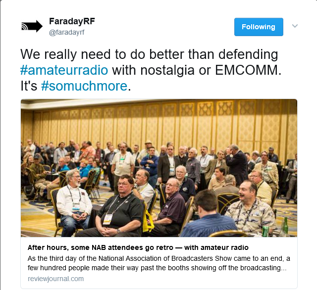 This refers to an article in the Las Vegas Review-Journal newspaper where the author decided to use the theme of “ham radio is retro” to tell the story of a ham radio gathering at NAB. I really hate it when ham radio gets positioned as “old technology” in the world of awesome wireless stuff. Clearly, some of our technology is dated, but the amateur service includes lots of new technology and experimentation. (Actually, the tone of the article was very positive, so we shouldn’t complain too loudly.)
So I replied, along with a few other folks:
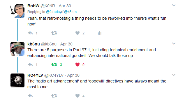 So KB6NU and KC4YLV took the discussion back to good old Part 97 of the FCC rules. (You ever notice how often radio hams like to quote Part 97? It’s right up there with the U.S. Constitution and the Declaration of Independence.) I tried to recall from memory the five things listed in 97.1 as the Basis and Purpose of the Amateur Radio Service, but failed.
I had to look them up, so I’ll save you the trouble and list them here. Actually, I am going to provide the KØNR Abbreviated Version (go here to see the full text):
Part 97.1 Basis and Purpose of Amateur Radio
a) Voluntary public service, including emergency communications
b) Advancement of the radio art
c) Advancement of communication and technical skills
d) Expansion of trained radio/electronics enthusiasts
e) Enhancement of international good will
These five things are still relevant and are being pursued today. Not all radio amateurs contribute to every one of these but as a group we are doing these things. The good news is that many non-hams do understand the When All Else Fails aspect of ham radio…most have had their cellphone become a useless brick during major incidents. Items b, c and d are all about learning new things, building skills and expanding the number of radio hams. We should talk more about that. Enhancing international good will may seem a bit quaint but this crazy world can always use another dose of that.
Part 97 does leave out one thing that is the ultimate attraction and, in fact, the universal purpose of ham radio:
To Have Fun Messing Around with Radios.
73, Bob KØNR
The post We’ve Got Some Explaining to Do appeared first on The KØNR Radio Site.
Bob Witte, KØNR, is a regular contributor to AmateurRadio.com and writes from Colorado, USA. Contact him at [email protected].
ETH067 – I Think I Have The PSK31 Bug Thanks to Ian Kahn, KM4IK

Over the past 67 episodes of my podcast, there has been a couple episodes that have really peaked my interest and kind of lit a fire under me to do whatever that topic is myself. Things like APRS back in episode 6, and Broadband Hamnet in episode 29. However, neither of those got me back onto HF. My HF rig has basically gone unused for close to seven years or so and has been in a box for the last three years!!
I honestly have never been big on voice communications on HF. All of the times that I have operated on HF has either been at home calling CQ or looking for someone else calling it or during things like Field Day. At home I rarely got anyone to answer my CQ call; I think I was getting out. During field day it was, basically the exchange and on to the next contact. Neither of these things were very fun to me.
Digital modes, especially thing like PSK31, seem to be right up my alley! So I decided to look for someone that knew something about it, that I could learn from. I finally found Ian Kahn, KM4IK and he agreed to come onto my show and talk to me about it. We had a great conversation and I learned a lot. If you are interested in learning about PSK31, head over to the show notes of the episode, you can listen right on the page, or you can search for Everything Ham Radio on the major podcast directories.
http://www.everythinghamradio.com/podcast/67
Curtis Mohr, K5CLM, is the author/owner of Everything Ham Radio Blog and Youtube channel. Contact him at [email protected].
I heard a loud bang!
 |
| Oliver likes the other use for the antenna cover |
 |
| The inside looked great |
Mike Weir, VE9KK, is a regular contributor to AmateurRadio.com and writes from New Brunswick, Canada. Contact him at [email protected].
I heard a loud bang!
|
| Oliver likes the other use for the antenna cover |
|
| The inside looked great |
Mike Weir, VE9KK, is a regular contributor to AmateurRadio.com and writes from New Brunswick, Canada. Contact him at [email protected].
Ham College 28
Safety Part 2 and more Technicians pool questions.
01:00:20
George Thomas, W5JDX, is co-host of AmateurLogic.TV, an original amateur radio video program hosted by George Thomas (W5JDX), Tommy Martin (N5ZNO), Peter Berrett (VK3PB), and Emile Diodene (KE5QKR). Contact him at [email protected].
Books
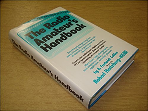
That habit stayed with me all my life. When I first became interested in Amateur Radio as a teenager in high school, my "bible" was "The Radio Amateur's Handbook" by Collins and Hertzberg. That book was my constant companion in my teen years and I must have read it, cover to cover, at least a half dozen times. It fueled my wishful dreams of becoming a Ham Radio operator, making contacts with people from all over the world.
I still have that book, and it holds a place of High Honor on my Amateur Radio book shelf.
A few weeks ago, I came home from work to see a rather large package sticking out of my mail box. As I was bringing it into the house, I noticed it was from Schiffer Publishing. I thought that this was kind of odd, as I hadn't ordered anything from Schiffer. After dinner, I opened the package to find a most wonderful book entitled "Compendium Of Automatic Morse Code". I couldn't believe my eyes! The book was sent for me to look over and to offer a review. It is a wonderful piece of work by Ed Goss N3CW. The amount of work and detail that he put into his book is phenomenal.
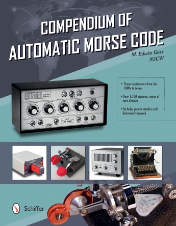
Granted, this is a niche book. Not every Amateur Radio operator will gravitate towards an edition like this. If you have a love for Morse Code and for the keyers, paddles and other devices that produce it, then this book is for you.
It is exhaustive in its content and detail and everything about this book screams "quality". From its size, 9 X 11 inches, to the feel of the heavy stock of the pages, to the rich and highly detailed color photography, everything about this book says, "Coffee Table Book for Ham Radio".
The table of contents includes chapters on
Chapter 1: An Overview of Telegraphy and Early Keys - History
Chapter 2 - Code Readers, Oscillators and Morse Trainers
Chapter 3 - The Electronic Keyer
Chapter 4 - The Single-Lever Paddle (Without a doubt, my favorite chapter!)
Chapter 5 - The Dual-Lever Paddle
Chapter 6 - Portable/Miniature/QRP Paddles (My second favorite chapter!)
Chapter 7: Commemorative Paddles
Chapter 8 - Combination Key and Paddles
Chapter 9 - Convertible Paddles and Paddle Modifications
Chapter 10 - Automatic Mechanical Keys
Chapter 11 - The Elements of Paddle Design
Chapter 12 - Paddle Adjustment and Maintenance
Chapter 14 - Telegraph Machines, Keyboard Keyers and Terminals
Chapter 15 - Computer Interfacing and the Internet
And various appendices and a bibliography as well as a list of recommended reading.
Pretty exhaustive, eh? If you're thinking,"Well really, how much is there to write about on this subject?" I'll answer that question by saying, "Over 300 pages, as a matter of fact!"
It's not hard to tell that writing this book was a labor of love for N3CW. It's one of the best if not THE BEST book to come down the pike on the subject. It has earned an honored place on my book shelf, right next to my beloved Hertzberg and Collins. However, I can tell you that it doesn't stay on the shelf for long. It has been in my hands a lot and will be for a long time to come.
I would highly recommend adding the "Compendium of Automatic Morse Code" to your Amateur Radio library if you're as much as a devotee of CW operating as I am. I can see this book as a golden answer to that age old question that every Ham gets asked every now and then ....... "Honey, is there any Ham stuff that you'd like for your birthday? Or Christmas, or Hanukkah, etc, etc, etc.
Thanks to Ed N3CW and Schiffer Publishing for sending me a copy! It was a very pleasant surprise and is appreciated more deeply than you will ever know.
72 de Larry W2LJ
QRP - When you care to send the very least!
Dit, dit!
Larry Makoski, W2LJ, is a regular contributor to AmateurRadio.com and writes from New Jersey, USA. Contact him at [email protected].
 Ham Radio Deluxe |
 W5SWL Electronics |
 Ham Radio Prep |
 KB3IFH QSL Cards  Hip Ham Shirts  HamRadioAuctions HamRadioAuctions Reliance Antennas Reliance Antennas Enigma Shop Enigma Shop |  morseDX  Ni4L Antennas  R&L Electronics R&L Electronics antennas.us antennas.us QRV QRV |
- Matt W1MST, Managing Editor
