 |
 The Montreal Doppler
 So, here I was at Dayton a few weeks ago and decided to check out the fox hunting/amateur radio direction finding (ARDF) forum. I forgot who did the forum, but it was actually very well done. One of the projects I learned about was “The Montreal Doppler”. This is a really neat project designed by Jacques Brodeur, VE2EMM.
I saw many neat attenuators, offset attenuators….. but this….. well…. it has LEDS! Pretty lights…. OK, I digress. Working with a bunch of these LED’s is pretty kewl and looks sweet. This is a project that is well documented on the web and I’ll provide links below.
The biggest question I had was, where do I get the microcontrollers and firmware. Not only was I able to acquire the PICS (microcontrollers), but I was able to get PC boards and the LCD for a very reasonable price from FAR Circuits! I know I picked up the last one he had at Dayton, but he may be able to do more (they cost $45.00). Check out the FAR circuits website at http://www.farcircuits.net/
A little about this project from VE2EMM’s website, list of features:
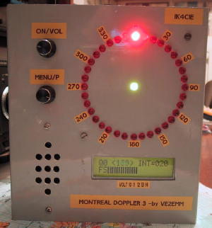
– 36 LEDs display; center LED when green = good signal, when red = no signal , the direction is frozen to the last good signal.
– Uses 3 PICs; a PIC16F628A for the display, a PIC18F4520 as the main processor and a PIC12F675 as a frequency divider.
– Filters; a Max 267, the best bandpass filter that I have ever seen, followed by the Roanoke switch cap filter for very narrow band width (+/- 0.5Hz).
– My DopplerII integrating and phase detection software in the main PIC.
– LM386 for monitoring the audio independently from the doppler.
– Simpler menu selection, turning a selection pot and a pushing a DO switch.
– It will switch 4 antennas with a + or – going signal, 4 antennas differential, 8 antennas with a + or – going signal.
– Pushing the DO PB sends the direction to APRS. The protocol is: <cr><lf>%359/Q<cr><lf>. The Q (0<8) is the quality of the signal just before the
extraction of the phase information.
– GPS information goes through the doppler, it will be instantly interrupted when the doppler sends a DF to APRS on a PC.
– Faster main processor, PIC18F4520. **** NEW **** June 06
The model I saw really intrigued me and there are a few really well done websites devoted to this project (it has quite the cult following).
The original site is at:
http://www.qsl.net/ve2emm/pic-projects/doppler3/doppler3-e.html
Here is another page on Jacques site that has some examples from other builders:
http://www.qsl.net/ve2emm/pic-projects/doppler3/md3_photos/dopler%203%20pictures.html
KA7OEI has a neat page with a bunch of information on this project:
He has a lot of information about an alternate firmware that looks like the image below:
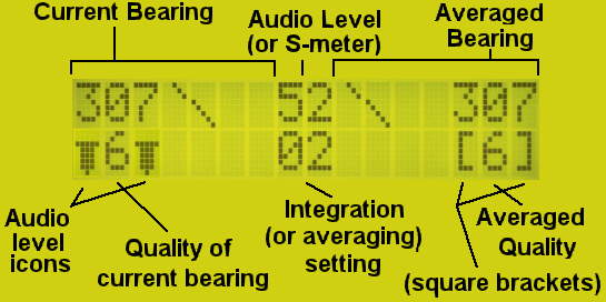
The alternate firmware page is at:
http://ka7oei.com/emm2_mont2a.html
If you have any more information on this project, resources or anything of the sort, please comment below.
Jonathan Hardy, KB1KIX, is a regular contributor to AmateurRadio.com and writes from Connecticut, USA. Contact him at [email protected].
One Foot in the Grave
This blog is meant to be about my hobby, amateur radio. Occasionally I have given in to the temptation to blog about some other event that has affected me, or let off steam about some topic that has annoyed me. But as I discovered a few months ago when a couple of the American ham radio blogs I read decided to vent about Obama, health care and other issues that Americans care deeply about, it can be very disconcerting to encounter far off-topic subject matter in a specialist blog, especially if the opinions expressed are ones with which you profoundly disagree. So in recent months I have tried to resist the temptation of controversial posts.
Sometimes I still get the urge to write about these topics, though. So to satisfy that urge I have started a new blog. Its title is One Foot in the Grave; the subtitle is Ramblings of a real-life Victor Meldrew. British readers who have seen the BBC comedy series of the same name will know what to expect from this. Readers from other parts of the world will have to see for themselves, though perhaps much of what I will be writing about won’t be of much interest to them anyway since it is going to be mostly about the trials and tribulations of life in the UK.
Nevertheless I hope that a few of you may find it worth following One Foot in the Grave and even telling other people about it.
Julian Moss, G4ILO, is a regular contributor to AmateurRadio.com and writes from Cumbria, England. Contact him at [email protected].
Handiham World for 16 June 2010
Welcome to Handiham World!
What coax should I use?

Question:
The repeaters I want to use are all just a bit too far away for me to work with an indoor antenna or a handheld radio. I want to install an outdoor antenna so that I can use several different VHF and UHF repeaters. I already have a dual-band 2m/70cm vertical antenna, but what kind of coax should I use? I am thinking about RG-58 or RG-8X, because they are cheaper and easy to work with than the thicker RG-8 or RG-213. My cable run will be about 100 feet.
Answer:
Since the repeaters you plan to work are probably located in different compass directions, your choice of a vertical antenna is a good one, as long as the repeaters are not so far away that you would need a directional antenna with more gain. The directional antenna usually means an extra investment in a rotator system, a considerable expense and an additional accessory to maintain over the ensuing years.
One thing you will not want to skimp on is your feedline, especially if it is to be used for VHF and UHF work, and when the feedline is going to be run for a considerable distance. A short run of RG-8X, under 25 feet, is probably acceptable for VHF work. The problem with these thin, cheaper feedlines is that they lose quite a significant amount of signal – both on receive and on transmit – and the savings in initial cost for the coax are quickly offset by the poor performance they introduce to your otherwise well-designed system. RG-58 is such thin, fragile coax that it is a poor choice for anything but temporary use or short connecting cables used in test situations. It is very lossy and should not be used over long runs, even for HF operation. Its fragility means that it can easily break.
Let’s take a look at the loss for a typical VHF frequency, 146.52 MHz for three common types of coax, all assuming a 100 foot run.
RG-58: Power in = 100 Watts. Power out = 34 Watts. Total loss is 4.7 dB. Ouch!
RG-8X: Power in = 100 Watts. Power out = 39 Watts. Total loss is 4.1 dB. Ouch!
RG-213: Power in = 100 Watts. Power out = 55 Watts. Total loss is 2.6 dB.
As you can see, the unfortunate truth is that all of these cables have significant loss, but the cheaper cables will end up turning most of your signal into heat. Only the RG-213 comes close to being acceptable for VHF use with a 100 foot run.
Now for something really scary, let’s try a 70cm frequency, 446.0 MHz, with the same cable run.
RG-58: Power in = 100 Watts. Power out = 13 Watts. Total loss is 8.9 dB. Double Ouch!
RG-8X: Power in = 100 Watts. Power out = 15 Watts. Total loss is 8.2 dB. Double Ouch!
RG-213: Power in = 100 Watts. Power out = 32 Watts. Total loss is 5 dB. Ouch!
Discussion:
Even with the best of these three coax types, you are still getting less than one third of your signal to the antenna. Remember that it works the same way on receive. And why would you even bother with RG-58 or RG-8X for UHF work, when 100 Watts turns into only 15 Watts or less? Long runs of cheap, lossy cable might as well just be dummy loads!
As you can see from the results we have listed, the loss per distance unit of feedline goes up when the frequency goes up. Therefore, a cheaper grade of feedline might be acceptable for use on 3.9 MHz, but far too lossy for use at VHF or UHF. Another consideration is that if one intends to use even higher transmit power levels, cheaper coax must not be used because it may arc over and fail. It is generally acceptable only for lower power levels.
The results we listed are for SWR readings that are virtually perfect, 1:1. Since no antenna installation is perfect and minor mismatches occur in even a carefully-designed system, the actual loss will be even higher than what we listed. This makes using good feedline even more important.
To summarize, you will have several important choices to make when you plan your VHF/UHF antenna system. You will want to decide which repeaters you want to work, their compass directions from your station, and whether you will need to choose a directional antenna or a vertical antenna. The supporting structure will add height, which is generally a good thing for effective VHF/UHF work, but also add to the length of a feedline, and longer feedline runs mean more loss. If you want to try weak-signal work on VHF and UHF, you will need a rotator and a horizontally-polarized directional antenna. Unlike repeater operation, weak signal work on SSB and CW absolutely demands good quality feedline for the lowest loss possible. FM repeater operation is less demanding, and will require vertical polarization. You may be able make your horizontally-polarized system work for repeaters, but your vertically-polarized antenna will not be effective for weak signal work on SSB and CW.
Our recommendation is to use good quality feedline for every installation, avoiding higher loss coax except for short connectors and temporary use in sort runs.
Resources:
Are you wondering how we calculated the loss for examples we used in this article? It was easy with the online calculator we found at the KC7HXC website!
For Handiham World, I’m…
Patrick Tice
[email protected]
Pat Tice, WA0TDA, is the manager of HANDI-HAM and a regular contributor to AmateurRadio.com. Contact him at [email protected].
A new article about APRS
![]() I have just added a new article to my website:
I have just added a new article to my website:
APRS – Putting ham radio on the map.
It’s quite a long article, but do read it if you have the time. I hope that it will explain what APRS is for to the many people who don’t seem to understand, and even more I hope it will encourage more people to try it.
If you like the article and think that it will help to spread the word about APRS, please post links to it anywhere you think would be appropriate.
Julian Moss, G4ILO, is a regular contributor to AmateurRadio.com and writes from Cumbria, England. Contact him at [email protected].
LHS Episode #041: Deep Thoughts
 If life would stop conspiring to halt production of Linux in the Ham Shack, everything would be just fine. Instead, because of problems in both our lives, the Dayton Hamvention and the Southeast Linux Fest, everything has been pushed back so far we feel like we’re going back in time.
Richard was unable to record for Episode #039, but luckily I was able to find a worthy surrogate for this particular show. Chris and Bryan over at The Linux Action Show had prior obligations and didn’t respond quick enough, respectively, but we hope to have them on a future episode. However, ClaudioM decided he didn’t have anything better to do and was able to swing by and offer his thoughts on a couple of intriquing concepts suggested by visitors to the Dayton Hamvention: 1) How do we promote Linux and Open Source and should it be promoted, and 2) Why does the perception that Linux is harder to use than Windows persist?
I found this to be a rather insightful episode and I hope you do as well. Thank you to everyone who visited Linux in the Ham Shack in Dayton and in Spartanburg, and please enjoy this latest installment of the program.
73 de The LHS Guys (and ClaudioM)
Russ Woodman, K5TUX, co-hosts the Linux in the Ham Shack podcast which is available for download in both MP3 and OGG audio format. Contact him at [email protected].
New APRS client for Linux
Linux users now have an alternative APRS client to Xastir. It’s called APRSIS32 for Win32. I have discovered that Lynn KD4ERJ’s Windows APRS client runs almost perfectly under the Linux OS using wine, the Windows compatibility layer.
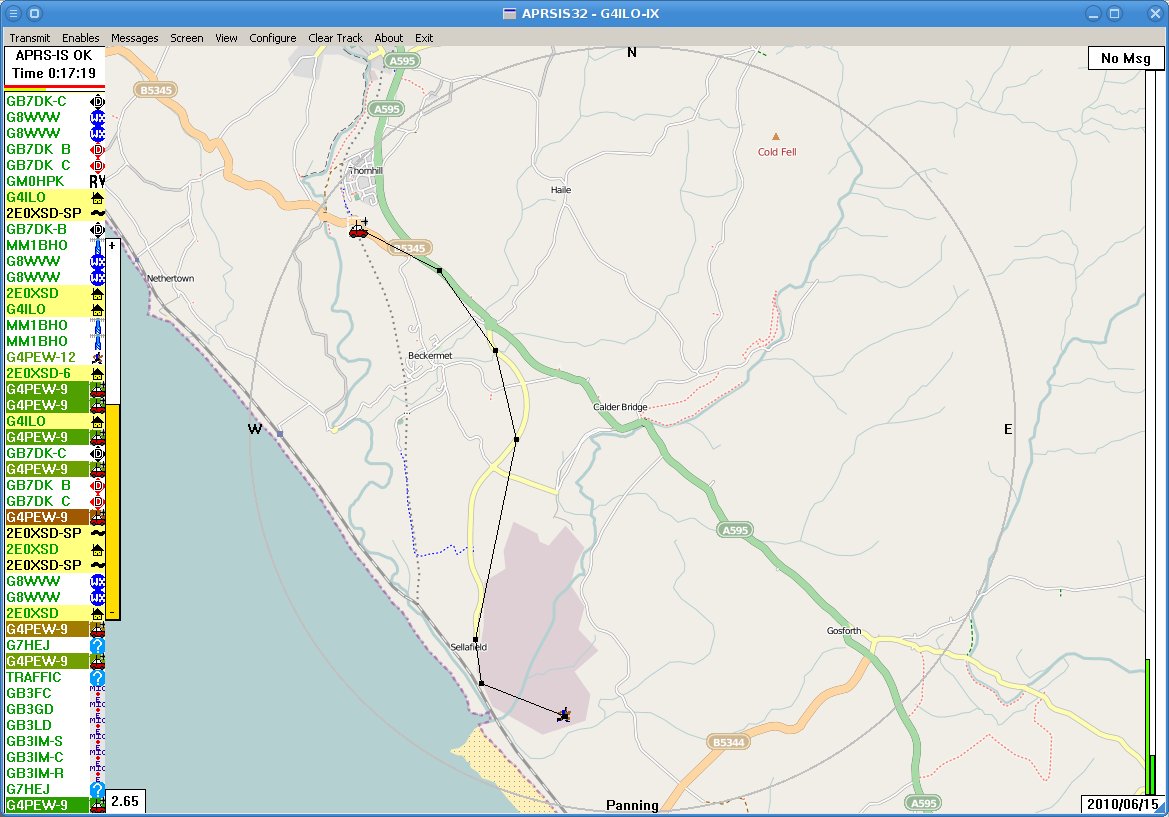 It’s pretty easy to get APRSIS32 going. Just download the Win32 version from the APRSISCE Yahoo group, save it into a folder somewhere under .wine/drive_C and run it. The program will start downloading maps so you can zoom in and set your home location. The only problem is, you can’t see them. By default the maps are displayed semi-transparent and it appears that wine doesn’t support transparency. So you will need to keep hitting the right arrow key which increases the opacity until the maps are 100% opaque, when they should appear. Check the APRSISCE/32 documentation wiki for more information.
There are a few screen redraw issues and the automatic updater always seems to fail, but these are minor issues. APRSIS32 uses code common with the APRSISCE version that runs on Windows CE mobile phones. These use a pretty small subset of the features available to current Windows software so by happy accident the program avoids doing things that wine doesn’t support which prevent more complex programs like Ham Radio Deluxe from working.
I haven’t tried the program with a GPS or a TNC as I don’t have them, but since these are just standard serial connections which are certainly possible under wine that is unlikely to be a problem. Lynn seems pretty keen to tackle the problems that I have discovered. In the meantime, the program still seems to work pretty well, so if you use Linux and are interested in APRS why not give APRSIS32 a try?
Julian Moss, G4ILO, is a regular contributor to AmateurRadio.com and writes from Cumbria, England. Contact him at [email protected].
Undesired attention
I wish Murphy, the patron saint of things that don’t work, would leave me alone. It’s a bit frustrating reading on other blogs that someone spent a weekend and ended up with some perfect working piece of gear while I spent several hours just trying to get a computer to talk to a radio.
Although APRSIS32 now supports transmit and receive using AGW Packet Engine which can use a soundcard as a modem I have never decoded a single packet, nor have my beacons been reported as heard by anybody. I started to wonder whether my cheap USB dongle – one of those things about the size of your thumb with a USB plug on one side and two 3.5mm stereo jacks on the other, that cost next to nothing – was up to the job. It had worked acceptably well for Echolink, but although my braaaps sounded to me like packet, they might not sound enough like packet to someone else’s decoder.
My computer’s on-board soundcard is in use by my K3 so there was no point in trying that. But I did have another slightly better USB audio dongle being used for PC sound, so I decided to swap them over. I removed the cheaper dongle in order to better access the audio sockets and when I replaced it I received a message from Windows that “One of the USB devices attached to the computer has malfunctioned” and it disappeared from the system. Giving up on computer sound for the moment I proceeded to try to test APRS packet transmission using the other dongle. But although I was receiving audio OK and keying the transmitter I was not transmitting any audio!
I fished the interface out from behind the rigs – a trying task ever since I installed the new shelving – in order to test it with my netbook and FT-817. It worked perfectly with Fldigi. Perhaps a bad connection? Back in position connecting the Icom to the shack computer and still no transmit audio, even though I could plug the computer speakers into the headphone output and hear the braaps being generated by the software!
Eventually it finally dawned on me that the AGWPE soundcard software only generates audio on the left channel. My radio interface was wired to the right channel! The cheapo USB audio dongle (that was now malfunctioning) presumably had a mono output so I was getting audio on both channels. The better one was generating proper stereo so there was no output on the channel I was using. D’oh!!
Fixing this ought to have been simple. Just open up the interface and switch the wires so the one from the left channel provides the input instead of the right one. But of course, it wasn’t. Even though the cable from the stereo jacks used in this interface had no less than four insulated wires within the screening, only one was connected to anything – the tip (right channel) of the plug. The ring was unconnected. So I had to take another audio patch lead, cut it in half, and use that to make new audio cables for the interface using the left hand channel.
Finally, it appears to be working, though I have still to decode an APRS packet. But now I have no computer audio because the other USB dongle is still broken and the connecting cable was cut in half to get the interface working. I came this –><-- close to saying "the hell with all this" and ordering a Signalink USB interface this morning.
Julian Moss, G4ILO, is a regular contributor to AmateurRadio.com and writes from Cumbria, England. Contact him at [email protected].
 Ham Radio Deluxe |
 W5SWL Electronics |
 Ham Radio Prep |
 KB3IFH QSL Cards  Hip Ham Shirts  HamRadioAuctions HamRadioAuctions Reliance Antennas Reliance Antennas Enigma Shop Enigma Shop |  morseDX  Ni4L Antennas  R&L Electronics R&L Electronics antennas.us antennas.us QRV QRV |
- Matt W1MST, Managing Editor
