 |
 No improvement
I know that one of the purposes of my website is meant to be to demonstrate that you can play ham radio even if you can’t have outside antennas. But sometimes the frustrations of not quite being able to achieve what you want to make become almost too much.
On Tuesday I replaced my home made ribbon cable Slim Jim 2m antenna with a commercial dual band colinear from Moonraker. I wasn’t sure the home made antenna was working as well as it possibly could. Originally I planned to replace the Slim Jim with a single band 5/8 wave Sirio, but after a month waiting for Radioworld to deliver it I cancelled the order and gave up. Then I got the Kenwood TM-D710 which is a dual band transceiver, so I decided I should have a dual band antenna to give me the option of running a public Echolink node on 70cm.
During the last few days I have been searching for signs of improvement in my 2m receive capability, but the signs haven’t been good. I’m hearing a frustrating number of APRS “braaps” that are just not strong enough to decode.
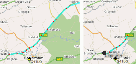
The antenna certainly works. I’m getting almost end-stop signals from the repeaters GB3DG and GB3LA, whilst GB3AS is about S5 with a bit of noise on it. I have had a couple of solid contacts using the antenna but nothing to form a basis for comparison until today, when Noel G4PEW drove past.
On the left of the screengrab you can see his track on Monday, when I was still using the Slim Jim. On the right you can see today’s track, received using the new antenna. It’s a lot shorter. I certainly heard a lot of packets after the last one shown by the grey blob, but none were strong enough to decode.
If only I could have the antenna outside the attic, up above the apex of the roof, I’m sure that extra little bit of height would make all the difference.
Julian Moss, G4ILO, is a regular contributor to AmateurRadio.com and writes from Cumbria, England. Contact him at [email protected].
APRSBB: APRS Client for Blackberry
I’m a big Blackberry fan and I was pretty excited to read G4ILO’s post a few days ago about APRSBB, a soon-to-be-released APRS client for Blackberry. I tracked down the developer, Chris Struttman KJ4HPQ of The Blue Array Network LLC, who agreed to be interviewed about what he’s been working on and what we can expect from the project:
Matt Thomas, W1MST, is the managing editor of AmateurRadio.com. Contact him at [email protected].
What Would You Do? Antenna ideas anyone?
We purchased our condo before I got back into ham radio. Like most in Orlando, we have antenna restrictions. I can put up portable or temporary antennas but cannot mount anything to the building permanently. I’d love to be able to get on the air without all the hassles of dragging gear to the porch, setting up an antenna and then tearing it all down again. It takes so much time to setup and tear down that it turns a few minutes of operating into a long process.
Here’s the layout I have to work with at the QTH…

The front yard view… I am next door down from the blue car

Preferred antenna site is the backyard
The buildings run north and south and these photos are shot facing due north. My condo is ground floor, second from the south end of the building. Yes, that is a big electrical transformer box and a major underground feeder line runs to it from the north.
I’ve used my Buddistick with some success but it doesn’t like being so close to the buildings and the swr is higher than when it is out in the open. I also have run a doublet inverted vee fed with twinlead but the north south orientation is not very favorable from my Florida QTH and sends most of my rf into the two buildings. My W3EDP works fairly well as an inverted L with my 20′ Jackite pole and I’ve used end fed halfwaves as slopers and inverted vees but again the directivity is not favorably oriented. I have a 3 foot magnetic loop propped against the wall but it is not working as well as I’d like yet. (i.e. the outdoor antennas work LOTS better so far)
Thought I’d ask ya’ll for some input.
Any outrageous ideas or thoughts for me? Send me a comment and let me know.
Thanks in advance for your thoughts.
Kelly McClelland, K4UPG, is a regular contributor to AmateurRadio.com and writes from Florida, USA. Contact him at [email protected].
Radio Three Four Papa
I downloaded the complete Radio Three Four Papa set at K5ZD’s website
as a learning tool. Athletes watch hours of video in order to gain an
understanding of their opponent’s skill and strategy. I lost a lot of
points last weekend when I failed to search for additional
multipliers. My Q count was sufficient however I did not log enough
mults when 15m opened to the east and midwest.
When do I shift from a calling CQ strategy to a search for multiplier strategy?
My NAQP rate was a thrill beyond 50 watts into a ground mounted
vertical. I blissfully called CQ while I heard in the corner of my
competitive mind, “Search for multipliers.”
I continued calling CQ instead of bagging a few 15m rhinos for the
long haul score. I’m listening intently to Radio Three Four Papa as
the team moves between CQ and hunting for multipliers. Rate is nearly
everything in RadioSport however an extra section or zone usually
decides a top ten finish.
73 from the anywhere, anytime shack.
Scot Morrison, KA3DRR, is a regular contributor to AmateurRadio.com and writes from California, USA.
Dual band rectangular loop antenna for 15m and 10m

The loop and the off-centre fed dipole at Field Day
This is the second article describing the two antennas that were used by the Carleton University Amateur Radio Club (CUARC) at Field Day 2010. The first post described an off-centre fed dipole with a 200 ohm feedpoint impedance. This post describes the second antenna a loop antenna that worked on two bands, 15m and 10m.
I like loop antennas. I have built large loops for amateur bands, as well as small loops for receiving (which are quite different to their bigger cousins) and have found both types perform well. They are less sensitive to local noise, so often giving good signal to noise ratios. As CUARC was to operate on 10m and 15m at the Field Day site I was considering a loop for one of these bands, however, which one? 10m could be fun if there was an opening, plus the antenna would be smaller than 15m. However, 15m would be more likely to be open. In searching the internet I came across a potential solution as KT4QW’s website who describes a 17m and 10m hanging loop antenna. The idea was simple and elegant, two vertical and rectangular loops fed from the same point, similar as to how multi-band dipoles can be fed from the same feedpoint (sometimes called a fan dipole).
I went about calculating the basic design. A full-wave loop’s total perimeter length is calculated by:
Length (in feet) = 1005 / f,
where f is the intended frequency of operation in MHz.
So for 21.3 MHz that would be a total loop length of 47.2ft and for 28.5MHz it would be 35.3ft.
To attain a 50Ω feedpoint the loop needs to be rectangular, with the longer length vertical. Studying J. Carr’s Loop Antenna Handbook and KT4QW’s dimensions the sides were close to being 1/3 of the total loop length for a vertical side and 1/6 for the horizontal side. So this then gave a design as shown below.

Dual band loop antenna for 15m and 10m.
To support the wire I bought two 10ft lengths of PVC piping. The inner support for the upper part of the 10m antenna was some thin wood. Both the wood and PVC were drilled with holes prior to Field Day. The wire was cut from a single 100ft roll and the whole antenna was built by CUARC members at the Field Day site on the day. At the feed point a 1:1 balun was used, an Elecraft BL2. The intention was to suspend the antenna from a single central point so the loop(s) could be rotated, using a line tied to one lower corner. However, we could not get enough height and clearance from tree branches, so we mounted it between two trees and it keep it static with the signal projecting in South-West and North-East directions.

The loops being connected to the balun by Gerry, VA3GLT (left) and Maria, VA3MMI, (right). (Photograph and copyright of Chris Weisner, VA3SM)
After construction the SWR was measured and found to be nicely below 2:1 for both bands (at least the lower part of 10m which is quite a wide band). As mentioned in the earlier post Maria, VA3MMI, brought a portable analyzer to the site on Sunday morning and the trace of the SWR profile is shown below. You can see the antenna has two nice dips in the SWR within the two bands. In an effort to see the usable bandwidth (below 2:1 SWR) the max SWR on the Y axis has be limited to 2.0:1.

10m and 15m dual band loop antenna SWR plot
To further examine the bandwidth of the two dips in SWR Maria, VA3MMI, set markers at the 2:1 points of the SWR curves. These are shown in the next two traces (one for each band). Both show good usable portions of the bands for phone, see the tables on the right of the trace. (Thanks to VA3MMI for the measurements and traces).

Bandwidth for 15m is 467kHz, starting at 21.1MHz

Bandwidth for 10m is 767kHz, starting at 28MHz
So, with the off-centre fed dipole and this dual loop antenna, CUARC constructed two antennas for Field Day that worked on 15m and 10m without the need of an antenna tuner unit. Performance was good on both antennas and I heard at least one comment that that we had a strong signal (we used 100W). During Field Day we made over 100 contacts on 15m and 16 contacts on 10m. Not bad, as for many of the CUARC members this was their first chance at operating on HF. It was enjoyable for the newly licensed CUARC members to build and then use the two antennas and to find both worked successfully. For me that was perhaps the highlight of 2010 Field Day.


![]()
Alan Steele, VA3STL, is a regular contributor to AmateurRadio.com and writes from Ottawa, Ontario. Contact him at [email protected].
TS-930S PA/PS Postscript
Long-time followers of the blog know that one of my TS-930S transceivers has been a money and time sink for about the past five years, fully 60% of the time I’ve owned it. So, if you haven’t been following the story over the past couple of months, I pretty much replaced (almost—get to this in a second) all of the electrolytic capacitors in the power supply and power amplifier, plus replaced the driver and final amplifier transistors. As I increased the drive past the point where I got 50 watts output, I started to get a lot of AC hum on the signal.
At first, I thought the hum might be associated with a low-frequency instability in the power amplifier. I read all the Helge Granberg articles I could find on the topic and tried all of the prescriptions he suggested. Last night, I even went so far as to tweak the feedback resistances in the PA stage to increase low-frequency stability. Still there. Finally, I measured the frequency of the AC hum—exactly 120 Hz—full-wave bridge rectifier leakage. Tonight, I pulled the power supply board out of the radio, which is a herculean task, by the way. There were still three small, insignificant-looking electrolytic capacitors that I hadn’t changed. I found two of them in my junk box and crossed my fingers on the third one (a 25 uF, 100-volt unit), leaving it in place. While I had it out, I also found and shunted a pair of dying PCB traces with pieces of wire.
After putting the board back into the radio, I disconnected the PA 28-volt line and powered it up. I checked the 28B voltage…right on 28.5 volts. So, I reconnected everything and it fired right up at 100 watts without the hum. Perseverance seems to have paid off. For now. I keep telling myself that the next time it breaks, I’m going to get a K3/100. But, I just can’t bear to buy a radio that’s worth more than my car.
Ethan Miller, K8GU, is a regular contributor to AmateurRadio.com and writes from Maryland, USA. Contact him at [email protected].
Signal Corps Training film for the SCR-694
Sorry for the delay….. the hazy days of summer yield to a LOT of amateur radio and public service events!!!!
Today, we take a trip back in history to the American Signal Corps. Here is a series I recently stumbled upon with training for the SCR-694. Interesting radio (kinda like one of the early “go-boxes”. I am amazed when I see these or similar at hamfests and people just pass them by – they’re interesting. Maybe I love the history behind our beloved hobby to much…… so I couldn’t resist.
Jonathan Hardy, KB1KIX, is a regular contributor to AmateurRadio.com and writes from Connecticut, USA. Contact him at [email protected].
 Ham Radio Deluxe |
 W5SWL Electronics |
 Ham Radio Prep |
 KB3IFH QSL Cards  Hip Ham Shirts  HamRadioAuctions HamRadioAuctions Reliance Antennas Reliance Antennas Enigma Shop Enigma Shop |  morseDX  Ni4L Antennas  R&L Electronics R&L Electronics antennas.us antennas.us QRV QRV |
- Matt W1MST, Managing Editor
