 |
 Handiham World for 02 May 2012
Welcome to Handiham World.

You can do it!
Today, just as we did last week, we are going to begin with Troubleshooting 101 as part of our initiative to help new ham radio operators (and even some of us older ones) learn how to do some basic troubleshooting for ourselves. Yes, it can be tempting to ask someone else to do things for us. This can become a bad habit when it keeps us from learning new things, especially things that we could – with a bit of practice – learn to do for ourselves. Knowing these basic things can serve us well in the future when no help is available. This next simple exercise is one that we will be practicing at this summer’s Radio Camp. You can do it yourself once you learn a few basics.
Troubleshooting 101

I have my General Class license now, so I decided to put up a vertical antenna, which I ground-mounted, in my back yard. I have checked the SWR (standing wave ratio) and it is practically one to one. It is grounded with a ground rod right near the feedpoint, and I have kept the grounding wire short. I am putting out plenty of power with my 100 watt rig, but I am having a hard time making contacts? What is wrong here?
Vertical antennas have long been the subject of derision in many amateur radio circles. It is practically an article of faith that “a vertical antenna is one that transmits equally poorly in all directions”. These operators have either tried vertical antennas themselves and had a poor experience or (more likely) they have heard some know-it-all pontificating on the awfulness of verticals and the awesomeness of just about any antenna other than a vertical.
Yes, the poor old vertical has gotten a pretty bad reputation. But is it justified?
I say no! And here’s why.
The most common vertical antenna design is an electrical quarter-wave long. This means that a simple 20 meter vertical will be on the order of 16 to 17 feet tall (5 meters). There is no problem ground-mounting a vertical in most locations, and this kind of antenna is sometimes disguised as a flagpole in places where there are restrictions on traditional antennas. A ground-mounted vertical will certainly have other advantages, too. It will not require an expensive tower or other supporting structure. It will be easy to install and work on if it needs maintenance or adjustment because you can reach it without any climbing. You can trench the coaxial feedline under the ground to keep it out of the way. If it is mounted in the back yard, it will probably not even be visible from the street. No wonder this simple antenna seems so attractive!
But let’s get back to your troubleshooting question. You have done well with your vertical antenna installation as far as it goes, but you have made a common mistake. You have assumed that a ground rod would suffice as a complete grounding system – but it won’t. When we work with RF (radio frequency) energy, we must remember that RF grounding is not the same as providing a simple electrical ground for low-frequency AC, DC, or lightning protection. Yes, a good electrical ground is an essential part of a well-designed antenna and feedline system. Now it is time to complete your vertical antenna installation with a good RF ground. That means installing radial wires extending from the base of the antenna outward in all directions. The ground rod should work as a common connection point. The coax braid is connected to the ground rod or the antenna’s mounting post, both of which are tied together with a stout, solid conductor.
What is happening in your antenna system is that lots of current is flowing in the vertical element right near the feedpoint. This is normal and expected. There is also a lot of current flowing in the ground beneath and around the antenna, outward in all directions. That is because a quarter-wave vertical is like one side of a dipole system, except that the ground makes up the other half of the dipole. If you recall your General Class studies, you will remember that current in a half wave dipole flows most strongly right near the feedpoint.
Now, answer me this: If you put up a dipole with one leg made of a fully-extended wire and the other a very short wire connected to a big resistor, do you think that dipole would work as well as a dipole with both legs made of wire?
No? Why not?
“Well”, you say, “It is obvious that the dipole with a big resistor in it will not work as well because there will be power lost in the resistor. The resistor will heat up, just like a dummy antenna.”
Yes, you are right! In fact, dummy load antennas are really nothing more than resistors designed to dissipate RF energy to keep it off the air while you run tests on a transmitter. A dummy load will have a near-perfect SWR, even though it is a resistor. Just because it has a low SWR does not mean that it is a good antenna. The problem with your vertical antenna system is that it is like that dipole with a resistor in one leg. The ground beneath the antenna has resistance to the flow of RF energy outward in all directions. The soil does have some conductivity, but it depends on moisture and composition. So the ground can be like a resistor. The ground rod you have installed goes straight down and does nothing to help RF flow in all compass directions outward near the surface of the ground.
The fix: A good radial system.
Radial wires are installed like the spokes of a wheel, outward from the grounded side of your antenna’s feedpoint. They can be cut to a quarter-wave length for every band you plan to operate (if your antenna is a multiband vertical) or – and this is more practical – to whatever length is convenient to fit into the space you have. Mind you, this goes only for a ground-mounted vertical in an area with normal to good soil conductivity. If you are mounting a vertical over quartz rock with almost no soil, the tuned radials might be necessary. If you are in the USA Midwest with its rich soil, you can probably get by with random length radials in your ground-mounted system. The reason is that conductive soil pretty much detunes the radials anyway, so there is nothing to be gained by carefully measuring them. In fact, since most of the RF current will be flowing right near the feedpoint, it makes sense to provide it with a low resistance path there, close to the antenna.
Why? Think of the formula power dissipated = current squared times resistance. The higher the resistance in the ground, the more power will be dissipated as heat. You don’t want that! What you want is for most of the power to be used to make contacts with other stations. The earthworms will be happier, too, because they don’t need the extra heat. If most of the current flows in the ground near the antenna, then THAT is where you need to put the most radial wire. I have always simplified this concept when teaching about vertical antennas by using the following practical example:
You have a coil of wire to use for radials. It is 100 feet long and will provide the radial system for your 20 meter band quarter-wave vertical. The question is which of these choices would be better:
A. One long radial that uses all 100 feet of wire.
B. Two 50 foot radials running in opposite directions.
C. Three 33 foot radials spaced 120 degrees apart.
D. Five 20 foot radials spaced at 72 degrees apart.
If you were thinking about losses near the feedpoint, you would probably pick answer D. The reason is that you are putting more wire near where the loss is actually happening! In fact, the thing with radials is “the more, the better”, not “the longer the better”. Of course you would not want to go to extremes and assume that 100 one-foot radials would work. But in the real world, you want to get more wire down in the ground near the feedpoint. A dozen radials work better than four.
Installing and testing the system:
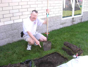
Stomp the grass back down and you are good to go. Repeat for each radial. If you can go out 33 feet in one direction and only 15 in another, that’s okay. Just make sure that the final installation is solidly connected to the ground rod and coax braid and all of the wires are out of the way of the lawn mower. The insulated wire will last longer in the ground than non-insulated wire. Once you get a taste of a hands-and-knees radial installation, you will not be eager to repeat it to replace rotted out wire any more than you have to. And if you tried to install springy radial wire, well, you know what that is like. Push one part in, another part pops out.
Email me at [email protected] with your questions & comments.
Patrick Tice, WA0TDA
Handiham Manager
Pat Tice, WA0TDA, is the manager of HANDI-HAM and a regular contributor to AmateurRadio.com. Contact him at [email protected].
The Man Who Fishes For DX
 |
| One of Dave's many QSL cards |
 |
| Red Wharf Bay, Anglesey |
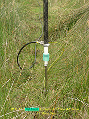 |
| Base section of carbon fibre vertical in situ |
Follow Dave’s simple formula and you too can become a fisher of men and the stuff of legend.
Rob Law, MW0DNK, is a regular contributor to AmateurRadio.com and writes from Anglesey, Wales. Contact him at [email protected].
New Summer Operating Event
I’ve been working with the leadership from the NJQRP club to start a new annual Summertime outdoor QRP operating event. My idea has earned their blessing.
Thanks to George N2APB and Joe N2CX, I will be announcing the details for the First Annual NJQRP Skeeter Hunt, in the next few coming days.
.jpg)
Stay tuned !
72 de Larry W2LJ
QRP – When you care to send the very least!
Larry Makoski, W2LJ, is a regular contributor to AmateurRadio.com and writes from New Jersey, USA. Contact him at [email protected].
Nice article
While strolling through the links at eHam, I came across this link to a very nice article about Rex Harper W1REX of QRPME fame:
On a KX3 note, a Ham friend of mine has decided that he and his XYL are not cut out for apartment living and have found themselves a small house to live in. Closing is near the end of this month. Right now it looks (as he described it) like a “horse race”. Which will occur first – arrival of the KX3 at W2LJ’s house – or my Ham buddy and his wife closing on their new house? My bet’s on them.
Hmmmmm …….. maybe I spoke to soon – this just came out on the KX3 reflector from Steve WG0AT:
Great News… Kit#1 to be Field Tested via kit assembly/manual …ships 05/02/12 tomorrow. Just heard from Bob/K6XX at Elecraft we’ve been asked to “Kit-test”, as in assemble, Kit# 1 using the latest rev of the kit manual and provide feedback on the process.
I’ve had Elecraft kit building experiences before with their K1, KX1, and K2 but not with any of their recent preassembled gear like a K3 etc. So it should be interesting to see how we do without the smell of a hot solder filling the room. (wonder if they sell solder scented candles aka Ham candle, Hah!)
My KX3-kit was originally destined for shipping via UPS ground but I thought 2-day air in this case would be a much better choice. (Next Day Air is ~$100!) 2nd Day air would get my kit here Friday PM. That’s assuming UPS does their job? Bob agreed and graciously offered to ante up the difference. This gives us the weekend to build and mark up the manual (if needed) and get the feed back to Elecraft before Monday (Maybe even as early as Sat? …no promises!).
Obviously at this point sooner is mucho better than later! (And no need to go into the waiting ‘whine’ song we all dread hearing! Instead …it’s soon over folks! – Peanut) So with any luck and we should be putting our brand new #1 Phillips to use this Friday PM! …YEEAH Baby!
Will keep you posted but if you hear silence for me Friday PM remember that’s a good sound! …Sri, no video – I want to focus on task! Video comes later.
Cheers, Steve …WGOAT/Rooster & Peanut
http://www.youtube.com/goathiker
http://w0-sota.org/
72 de Larry W2LJ
QRP – When you care to send the very least!
Larry Makoski, W2LJ, is a regular contributor to AmateurRadio.com and writes from New Jersey, USA. Contact him at [email protected].
Neat Find in the QST Archives
When I was a boy my father paid for my membership in the ARRL, but when I got out on my own I let my membership lapse because of the cost. When I finally joined again last year, I mainly did it so I could use the outgoing QSL bureau. Since then, however, I have come to appreciate other benefits of membership. One of those benefits is full access to the QST Archives. They are a treasure-trove!
The other day while doing a little research for some blog posts that are in the hopper, on a whim I searched for “Granite Falls,” the small town where I live. Sure enough, I got a hit — from September, 1969. It’s just one photo and a caption, but it’s an eye-opener. It shows that once upon a time Amateur Radio was used in an emergency here. For sure I’ll be showing this to the Emergency Manager in our county:

September, 1969 issue of QST, p. 66. Copyright © 2012 American Radio Relay League, Inc. – All rights reserved.
Using QRZ.com I looked up the fellow on the right, WAØJRA, and sent him an email inquiring about Amateur Radio here in Granite Falls back in those days. I’m looking forward to his reply.
Have you searched the QST Archives for references to your own city? Try it!


![]()
Todd Mitchell, NØIP, is a regular contributor to AmateurRadio.com and writes from Minnesota, USA. He can be contacted at [email protected].
As the skyline changes…

One World Trade Center
Here in Manhattan, the highest point above the hustle and bustle, is the Empire State Building. Or, it was at least until yesterday. As of April 30th, 2012, the new One World Trade Center is officially the tallest building in Manhattan. As I listened to the news yesterday morning this got me thinking about the antennas on the Empire State Building, and the logistics and history of them. For those of you fascinated by these things, here are a collection of resources to consult, and some of what I learned about the tallest antennas in the city.
I found a great article on the history of the TV mast at www.lnl.com/esbantennas.htm. The TV antenna portion was originally a mooring mast for dirigibles which was re-purposed 8 months after the building was completed in 1931. The article was a reprint from Broadcast Engineering magazine, August 1967. The mooring mast, which was part of the original design of the building, was supposed to be used by passenger airships for anchoring, while the passengers disembarked down a gangplank to the 102nd floor. In reality, this proved to be unsafe, as the updrafts and other air currents around the building would not allow for safe mooring. Only one dirigible ever successfully anchored to the mast after a 30 minute ordeal with mooring ropes, and even then was only able to stay anchored for 3 minutes. The first entity to transmit from the re-purposed mast was NBC who began experimental TV transmissions from the ESB in December of 1931. For you fans of TV’s Fringe, the sequences shot in the alternate universe, show modern dirigibles moored to the Empire State Building, as well as a skyline that still contains the Twin Towers.
Here also, is another great article; from CQ Amateur Radio, March 2011, Digging Deeper With Bill Baker, W1BKR, where Bill visits the transmitter site for channel 13, WNET, in the Empire State Building. Great pictures of the mast, and of the massive filter network that all signals have to pass through first to reduce interference with each other.
Today there are over 130 antennas on the Empire State Building at various heights. This site lists the options available to anyone interested in locating an antenna up there. I’m not sure how many Amateur Radio repeaters are on the building as of today, but one I know for sure is KQ2H. KQ2H has a large linked network of repeaters that give it incredible range, including a 10 meter input up in the catskill mountains. I can listen to the ESB 220, 440, and 900 repeaters from my desk at work, and get an idea of what’s going on with 10 meter propagation by taking note of where the incoming stations are. Lately I’ve been hearing hams from Australia and New Zealand hitting the repeater late nights between 8 and 10 PM EDT. KQ2H’s 10 meter FM machine transmits on 29.620, and listens on 29.520. It is usually available on EchoLink, although the link has been down lately. On EchoLink you need to search for the callsign W2FLA which belongs to the linked 2 meter repeater in the system up in the mountains.

Antenna Mast at the E.S.B. from CQ, March 2011 "Digging Deeper with Bill Baker"
Many of these entities that have antennas on the ESB, relocated there after the Twin Towers fell in the 9/11 disaster. I was looking for antenna leasing info for the new One World Trade Center building, but nothing seems to be posted yet. There is definitely going to be an antenna structure on the top of the building though. I’d love to take a couple of radios up to the ESB observation deck sometime, but I hear the officials can be a little touchy about these things (understandably so). As I learn more about One World Trade Center I’ll post it at a future date.
Does anyone else out there have stories about antennas on skyscrapers (like the former Sears Tower in Chicago, or even the CN Tower in Toronto)? Leave some info in the comments. 73.
–Neil W2NDG
Neil Goldstein, W2NDG, is a regular contributor to AmateurRadio.com and writes from New York, USA. Contact him at [email protected].
2012 Challenge – QSO A Day – Q1 + April
Q1 plus one (April) equals four months of at least one QSO per day in 2012. While April won’t break any QSO records, it was still a very busy and productive month.
While my QSO a day project is just that, having an on-air QSO each and every day in 2012, I had a few other notables I wanted to mention. In addition to my blogging and podcasting efforts, I’m also active in Summits On The Air (SOTA) and serve as regional manager for the central portion of Colorado (W0 region). Part of my responsibility is to promote Summits On The Air and by doing so I conducted three presentations in April. Two of the three presentations were to local amateur radio clubs in the greater Denver area and the third was via Skype to an ARC in Washington state. One of the local SOTA presentations included a demonstration activation which I conducted. I also completed a second SOTA activation on my own. Between the two SOTA activations, this netted 26 QSO’s.
I also spent a few hours working QSO party stations in both the Missouri and Florida QSO parties. QSO party QSO’s totaled 35.
Finally, in addition to the presentations and conducting at least one QSO per day in April. I also worked several weekends on the basement ham shack project. The basement ham shack is coming together nicely. We have all the drywall boards on the walls and ceiling and starting on the taping, mudding and sanding of joints and screw holes. This is what I’ve often referred to as the “messy phase”. But this work must be done before we can get to the painting phase. I’m hopeful by the end of May we will be ready to paint.
Stay tuned as I hope to complete at least one SOTA activation in May. Also, I’m working on some really cool content for episode 55 of PARP. I plan to get this episode out prior to Dayton.
The breakdown for April is as follows:
Mode
Number QSO’s
JT65
31
SSB
64
Additional notes of interest:
DX Stations Worked – 3
New DX Entities – 1
Total QSO’s for 2012 – 478
Total consecutive QSO days – 121
Days left in 2012 – 245
Until next time…
73 de KD0BIK
Jerry Taylor, KD0BIK, is a regular contributor to AmateurRadio.com and writes from Colorado, USA. He is the host of the Practical Amateur Radio Podcast. Contact him at [email protected].
 Ham Radio Deluxe |
 W5SWL Electronics |
 Ham Radio Prep |
 KB3IFH QSL Cards  Hip Ham Shirts  HamRadioAuctions HamRadioAuctions Reliance Antennas Reliance Antennas Enigma Shop Enigma Shop |  morseDX  Ni4L Antennas  R&L Electronics R&L Electronics antennas.us antennas.us QRV QRV |
- Matt W1MST, Managing Editor
