 |
 Nice addition to the kit roundup
I constantly search for new kit sources for the kit roundup list. Today I stumbled on this one:

Kit Radio Company KRC-1
–Kit Radio Company – KRC Kits. http://kitradio.co.uk/page2.htm This UK-based company produces several interesting kits including receivers,
transmitters, and accessories. All prices are in British Pounds.
- KRC-1 superhet receiver. This receiver covers MW, and SW (160 thru 40 meters). Built in a 5-stage process for education. 1) Medium wave TRF receiver driving an earphone. 2) Audio amplifier providing speaker output. 3) The TRF receiver is converted to an IF amplifier 4) Mixer/oscillator converting the receiver to a four band superhet. 5) BFO to enable CW/SSB to be resolved. £65.99 plus S&H
- KRC-2 regenerative receiver. Covers 1-30 Mhz. in 3 bands. Regeneration with a difference. The regeneration setting on the KRC-2 is unaffected by the receiver tuning or the antenna coupling. How is this achieved? The regenerative stage is fixed at 10.7MHz and used as an IF amplifier. This one reminds me of the Radio Shack Globe Patrol regenerative I built as a kid. £54.99 plus S&H
- KRC-4 beginners TRF receiver. 2 bands; 800KHZ to 1.6MHZ and 4.0 to 8.0MHz. A TRF receiver designed for the beginner. Using a reflex circuit this receiver employs only one transistor. Band selection is achieved with two plug in coils, these are pre-wound and both coils come as part of the kit. £24.99 plus S&H
- KRC-5 direct-conversion 80 meter receiver. Designed around two well proven chips the SA602 and LM386. Employing a VFO that can be calibrated to fulfill your requirements. £25.99 plus S&H
- KRC-X-1 QRP transmitter. Covers 7, 10 and 14MHz. All you do is plug in a different crystal assembly to change band and re-tune the antenna. 0.5 to 2 watts output. £69.99 plus S&H
- KRC-X-2 80/160 meter transmitter. A simple cost effective transmitter covering either the 80 or 160 meter bands. It provides 2 Watts of RF power when operating from a 12 Volt supply. With a peak output rising to 8 Watts if external modulation is applied. Please specify 160 or 80 meters when ordering. £33.99 plus S&H

Kit Radio Company KRC-X-2
Neil Goldstein, W2NDG, is a regular contributor to AmateurRadio.com and writes from New York, USA. Contact him at [email protected].
Severe case of Dayton envy!
I really envy all of you fortunate enough to attend the Dayton Hamvention and FDIM. Looks like a bounty of good QRP stuff will be available. Doug Hendricks KI6DS, posted this to QRP-L today:
Hendricks QRP kits will be at Dayton again this year, and we will be in a new location. Our booth numbers are 459 and 460, located right across from the ARRL in the Ball Arena. And we have 9 new products, yes, you read it right, 9. Here they are:
1. The Weber Tribander designed by Steve Weber, KD1JV. This is a 3 band CW Transceiver and you get to pick your bands from the following: 15, 17, 20, 30, 40 and 80 Meters. Digital display, Custom Case, DDS Vfo, and Encoder Tuning. If you have wanted a PFR on other bands or with rotary encoder tuning, this is the radio for you. Price: $200.
2. The Tuthill 160 designed by Dan Tayloe. Finally, a cw transceiver kit for 160M. We have expanded the popular Tuthill series to now include 160M with a full 5 Watts of output. Basic Kit is $100 (show special), optional Digital Display, $35. Now is the time to get this kit so you will be ready for 160 in the fall.
3. SMK-2. The popular surface mount 40M CW transceiver designed by Dave Fifield is back. And it is improved! The SMK-2 comes with 2 Frequencies, and is complete with case and connectors. Plus there is an optional Crystal Board available for switchable frequencies. The Transceiver is $40, Optional Crystal Board is $10. Frequencies are 7.030, 7.040 and 7.122MHz.
4. 41dB Step Attenuator. We have kitted the popular design that has been in the ARRL handbook for years. Ken Locasale designed a great looking case, and everything is included. Great for working low power and for transmitter hunts. $50.
5. Rock Hunter Chassis for the DCxxB series. We now have a case, connectors and an addon board to give 2 additional frequencies for the DCxxB series of transceivers. We have had many, many requests for a case for the DCxx series of transceivers, and now we have it. $20 for the case, connectors, controls and addon frequency board.
6. Red Hot 40 Transceiver. We will have a special price on the Red Hot 40, the high performance 40 Meter CW Transceiver designed by Dave Fifield. The show special is $200, which is $50 off the regular price.
7. Repackaged Tayloe SWR Meter. Ken has come up with a great little chassis for the SWR Meter designed by Dan Tayloe, N7VE. $25.
8. Sota Tuner. This has been one of our best sellers since we introduced it in September. The Sota is an End Fed Half Wave Tuner with a metal case, stainless steel hardware, and only weighs 2.5 ounces, and the price is $30.
9. Two Fer Transmitter. The Twofer is a great little transmitter. Available on 40 or 30 or 20 Meters. Show special at $30.
We will also have show specials on the Tenna Dipper, with a price of $70, MMR40 at $175, NADC40 basic kit w/out digital display, $100, Ft. Tuthill 15, basic kit no display, $100.
Stop by the booth and say hello to Steve Weber, KD1JV who will be in the booth on Friday and Saturday, plus Dean Davis, Darrel Swenson, Ken and Karen Locasale.
Plus, we will be able to take credit cards this year for the first time. We accept Visa, Mastercharge, Discover and American Express. I am kitting like crazy and really excited about this year at Dayton. Hope to see you there. Doug
Sounds like it’s a good idea to bring lots of radio money along. Maybe it’s a good thing that I’m not going? At least that’s what the XYL is probably thinking.
72 de Larry W2LJ
QRP – When you care to send the very least!
Larry Makoski, W2LJ, is a regular contributor to AmateurRadio.com and writes from New Jersey, USA. Contact him at [email protected].
First 70 MHz Es opening this year
I was working from home this afternoon and unfortunately, whilst I was on a call, there was a 70MHz opening to Finland! I managed to catch ES3RF on 50MHz after I finished the call.
I kept an eye on 70MHz though and a bit later, I heard my neighbour G4BRK calling something. Switched the 70MHz aerial onto the FT847 and I could hear some weak SSB on 70.200. It got louder and proved to be Ivan, S51DI! A few stations worked him in front of me, but in typical ES style, the signals built up to S9 and I was able to complete the QSO.
I’ve worked Ivan plenty of times on 70MHz of course, but it’s always great to get the first Es QSO on the band for the year in the log.
Down in the beacon band on 70.059 I heard the HG1BVC beacon for the first time.
Tim Kirby, G4VXE, is a regular contributor to AmateurRadio.com and writes from Oxfordshire, England. Contact him at [email protected].
Ham Nation 46

http://dts.podtrac.com/redirect.mp4/twit.cachefly.net/video/hn/hn0046/hn0046_h264b_864x480_500.mp4
http://dts.podtrac.com/redirect.mp4/twit.cachefly.net/video/hn/hn0046/hn0046_h264b_640x368_256.mp4
http://www.podtrac.com/pts/redirect.mp3/twit.cachefly.net/hn0046.mp3
Hosts: Bob Heil (K9EID), Gordon West (WB6NOA), and George Thomas (W5JDX)
Kids talk to the ISS, an educational hamfest, transferring a CAD drawing to a PC board with toner, and more.
Guests: Clint Bradford (K6LCS), Tim Duffy (K3LR), Don Arnold (W6GPS), and Julian Frost (N3JF)
Download or subscribe to this show at http://twit.tv/hn.
We invite you to read, add to, and amend our show notes at wiki.twit.tv.
Thanks to Joe Walsh who wrote and plays the Ham Nation theme.
Thanks to Cachefly for the bandwidth for this show.
Dr. Bob Heil, K9EID, is the founder of Heil Sound and host of TWiT.tv's Ham Nation which streams live each Tuesday at 6:00pm PT (9:00pm ET) at http://live.twit.tv. Contact him at [email protected].
Handiham World for 02 May 2012
Welcome to Handiham World.
You can do it!
Today, just as we did last week, we are going to begin with Troubleshooting 101 as part of our initiative to help new ham radio operators (and even some of us older ones) learn how to do some basic troubleshooting for ourselves. Yes, it can be tempting to ask someone else to do things for us. This can become a bad habit when it keeps us from learning new things, especially things that we could – with a bit of practice – learn to do for ourselves. Knowing these basic things can serve us well in the future when no help is available. This next simple exercise is one that we will be practicing at this summer’s Radio Camp. You can do it yourself once you learn a few basics.
Troubleshooting 101

I have my General Class license now, so I decided to put up a vertical antenna, which I ground-mounted, in my back yard. I have checked the SWR (standing wave ratio) and it is practically one to one. It is grounded with a ground rod right near the feedpoint, and I have kept the grounding wire short. I am putting out plenty of power with my 100 watt rig, but I am having a hard time making contacts? What is wrong here?
Vertical antennas have long been the subject of derision in many amateur radio circles. It is practically an article of faith that “a vertical antenna is one that transmits equally poorly in all directions”. These operators have either tried vertical antennas themselves and had a poor experience or (more likely) they have heard some know-it-all pontificating on the awfulness of verticals and the awesomeness of just about any antenna other than a vertical.
Yes, the poor old vertical has gotten a pretty bad reputation. But is it justified?
I say no! And here’s why.
The most common vertical antenna design is an electrical quarter-wave long. This means that a simple 20 meter vertical will be on the order of 16 to 17 feet tall (5 meters). There is no problem ground-mounting a vertical in most locations, and this kind of antenna is sometimes disguised as a flagpole in places where there are restrictions on traditional antennas. A ground-mounted vertical will certainly have other advantages, too. It will not require an expensive tower or other supporting structure. It will be easy to install and work on if it needs maintenance or adjustment because you can reach it without any climbing. You can trench the coaxial feedline under the ground to keep it out of the way. If it is mounted in the back yard, it will probably not even be visible from the street. No wonder this simple antenna seems so attractive!
But let’s get back to your troubleshooting question. You have done well with your vertical antenna installation as far as it goes, but you have made a common mistake. You have assumed that a ground rod would suffice as a complete grounding system – but it won’t. When we work with RF (radio frequency) energy, we must remember that RF grounding is not the same as providing a simple electrical ground for low-frequency AC, DC, or lightning protection. Yes, a good electrical ground is an essential part of a well-designed antenna and feedline system. Now it is time to complete your vertical antenna installation with a good RF ground. That means installing radial wires extending from the base of the antenna outward in all directions. The ground rod should work as a common connection point. The coax braid is connected to the ground rod or the antenna’s mounting post, both of which are tied together with a stout, solid conductor.
What is happening in your antenna system is that lots of current is flowing in the vertical element right near the feedpoint. This is normal and expected. There is also a lot of current flowing in the ground beneath and around the antenna, outward in all directions. That is because a quarter-wave vertical is like one side of a dipole system, except that the ground makes up the other half of the dipole. If you recall your General Class studies, you will remember that current in a half wave dipole flows most strongly right near the feedpoint.
Now, answer me this: If you put up a dipole with one leg made of a fully-extended wire and the other a very short wire connected to a big resistor, do you think that dipole would work as well as a dipole with both legs made of wire?
No? Why not?
“Well”, you say, “It is obvious that the dipole with a big resistor in it will not work as well because there will be power lost in the resistor. The resistor will heat up, just like a dummy antenna.”
Yes, you are right! In fact, dummy load antennas are really nothing more than resistors designed to dissipate RF energy to keep it off the air while you run tests on a transmitter. A dummy load will have a near-perfect SWR, even though it is a resistor. Just because it has a low SWR does not mean that it is a good antenna. The problem with your vertical antenna system is that it is like that dipole with a resistor in one leg. The ground beneath the antenna has resistance to the flow of RF energy outward in all directions. The soil does have some conductivity, but it depends on moisture and composition. So the ground can be like a resistor. The ground rod you have installed goes straight down and does nothing to help RF flow in all compass directions outward near the surface of the ground.
The fix: A good radial system.
Radial wires are installed like the spokes of a wheel, outward from the grounded side of your antenna’s feedpoint. They can be cut to a quarter-wave length for every band you plan to operate (if your antenna is a multiband vertical) or – and this is more practical – to whatever length is convenient to fit into the space you have. Mind you, this goes only for a ground-mounted vertical in an area with normal to good soil conductivity. If you are mounting a vertical over quartz rock with almost no soil, the tuned radials might be necessary. If you are in the USA Midwest with its rich soil, you can probably get by with random length radials in your ground-mounted system. The reason is that conductive soil pretty much detunes the radials anyway, so there is nothing to be gained by carefully measuring them. In fact, since most of the RF current will be flowing right near the feedpoint, it makes sense to provide it with a low resistance path there, close to the antenna.
Why? Think of the formula power dissipated = current squared times resistance. The higher the resistance in the ground, the more power will be dissipated as heat. You don’t want that! What you want is for most of the power to be used to make contacts with other stations. The earthworms will be happier, too, because they don’t need the extra heat. If most of the current flows in the ground near the antenna, then THAT is where you need to put the most radial wire. I have always simplified this concept when teaching about vertical antennas by using the following practical example:
You have a coil of wire to use for radials. It is 100 feet long and will provide the radial system for your 20 meter band quarter-wave vertical. The question is which of these choices would be better:
A. One long radial that uses all 100 feet of wire.
B. Two 50 foot radials running in opposite directions.
C. Three 33 foot radials spaced 120 degrees apart.
D. Five 20 foot radials spaced at 72 degrees apart.
If you were thinking about losses near the feedpoint, you would probably pick answer D. The reason is that you are putting more wire near where the loss is actually happening! In fact, the thing with radials is “the more, the better”, not “the longer the better”. Of course you would not want to go to extremes and assume that 100 one-foot radials would work. But in the real world, you want to get more wire down in the ground near the feedpoint. A dozen radials work better than four.
Installing and testing the system:
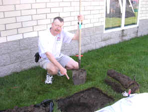
Stomp the grass back down and you are good to go. Repeat for each radial. If you can go out 33 feet in one direction and only 15 in another, that’s okay. Just make sure that the final installation is solidly connected to the ground rod and coax braid and all of the wires are out of the way of the lawn mower. The insulated wire will last longer in the ground than non-insulated wire. Once you get a taste of a hands-and-knees radial installation, you will not be eager to repeat it to replace rotted out wire any more than you have to. And if you tried to install springy radial wire, well, you know what that is like. Push one part in, another part pops out.
Email me at [email protected] with your questions & comments.
Patrick Tice, WA0TDA
Handiham Manager
Pat Tice, WA0TDA, is the manager of HANDI-HAM and a regular contributor to AmateurRadio.com. Contact him at [email protected].
The Man Who Fishes For DX
 |
| One of Dave's many QSL cards |
 |
| Red Wharf Bay, Anglesey |
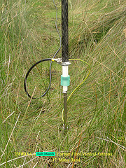 |
| Base section of carbon fibre vertical in situ |
Follow Dave’s simple formula and you too can become a fisher of men and the stuff of legend.
Rob Law, MW0DNK, is a regular contributor to AmateurRadio.com and writes from Anglesey, Wales. Contact him at [email protected].
New Summer Operating Event
I’ve been working with the leadership from the NJQRP club to start a new annual Summertime outdoor QRP operating event. My idea has earned their blessing.
Thanks to George N2APB and Joe N2CX, I will be announcing the details for the First Annual NJQRP Skeeter Hunt, in the next few coming days.
.jpg)
Stay tuned !
72 de Larry W2LJ
QRP – When you care to send the very least!
Larry Makoski, W2LJ, is a regular contributor to AmateurRadio.com and writes from New Jersey, USA. Contact him at [email protected].
 Ham Radio Deluxe |
 W5SWL Electronics |
 Ham Radio Prep |
 KB3IFH QSL Cards  Hip Ham Shirts  HamRadioAuctions HamRadioAuctions Reliance Antennas Reliance Antennas Enigma Shop Enigma Shop |  morseDX  Ni4L Antennas  R&L Electronics R&L Electronics antennas.us antennas.us QRV QRV |
- Matt W1MST, Managing Editor
