 |
 Making use of Elecraft Mini-module Kits
Connecting the bits and bobs
I have enjoyed building Elecraft Mini-Module kits. Now to put them to use...
 |
| Elecraft Mini-Module Kits |
What to do?
I built the kits as part of my learning adventure and to improve my soldering skills. It's also helped me learn to follow instructions better (my wife says I need to work on learning to follow instructions). But ultimately these modules are intended to be useful, and in my case they work nicely to when operating my old Ten-Tec Century/21.
My Ten Tec Century/21 is a 1970s CW-only, low(ish) power rig originally intended for Novice license holders of the time. It has no RF output meter or SWR meter. It has poor filtering/selectivity compared to modern radios and its analog tuning dial is a bit vague so you generally only know your frequency within 5 kHz.
The mini-module kits prove useful. I employ the W1 Wattmeter to determine my power output and SWR; the CP1 directional coupler is used to send a 20db attenuated signal to a frequency counter to determine operating frequency, and the AF1 Audio Filter makes operating near adjacent CW signals more pleasant by providing a narrow audio-band-pass filter. The result signal can be transmitted through a LDG tuner into the BL2 switchable balun connected to my attic Doublet.
Bring out your cables
All these independent modules need to be connected, so tying the bits and bobs together requires a few coax jumpers to route the RF around:
- UHF to BNC from the radio to the W1 Power meter
- BNC to BNC From the W1 Power meter to the CP1 coupler
- BNC to UHF From the CP1 coupler J1 input to switched T1 output to frequency counter
- BNC to UHF From the CP1 coupler J2 output to the tuner
And other cables:
- Serial cable from the W1 Power meter to the computer
- 12v power cables for the W1 and AF1 (unless I want to use 9V batteries)
- Audio cable from the TenTec C21 to the AF1
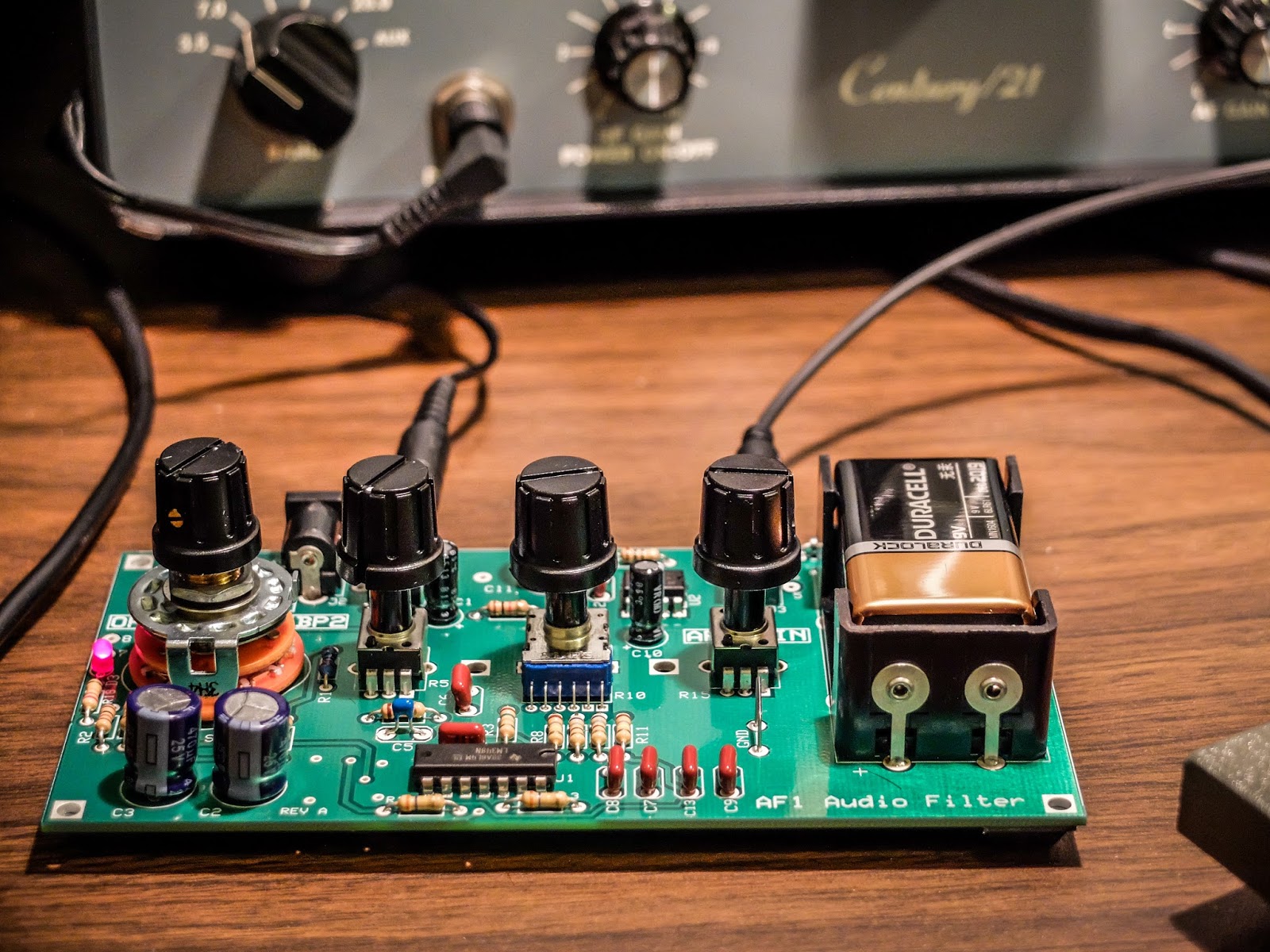 |
| AF1 Audio Filter making crowded band operations pleasurable |
 |
| CP1 Directional Coupler sending off 20dB attenuated signal to the frequency counter |
 |
| Frequency Counter fed by the CP1 directional coupler. |
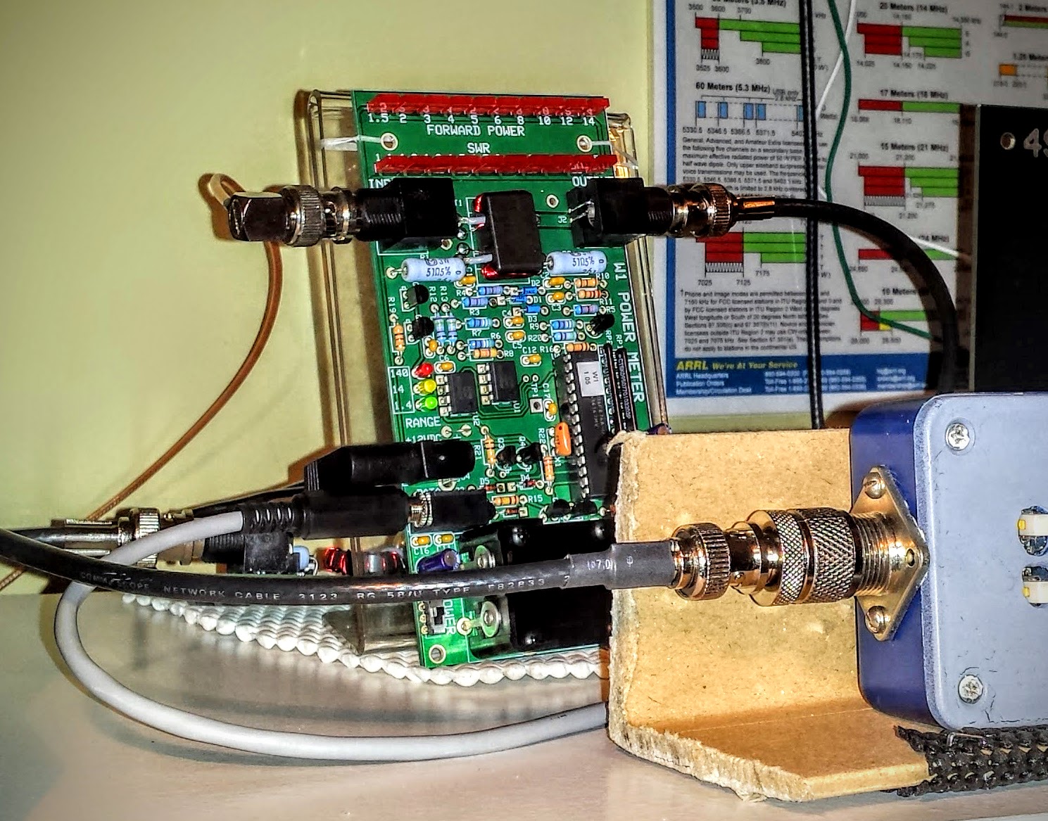 |
| W1 Power Meter sending its measurement off to the computer |
W1 Power Meter Output to Computer
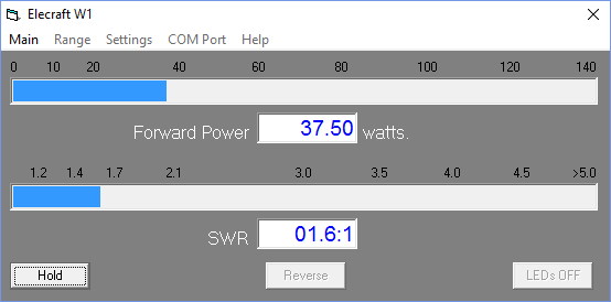
The W1 has a serial output to a PC for use with the Elecraft W1 software. The software can both configure the meter and display more detail than can be determined from the LEDs. Source code is supplied and the command set is documented so it would be easy to write your own software for this.
The W1 power meter LEDs give you relatively discrete output information for the lower two ranges (0.1w to 1.4w) and (1.5w to 14w). But in the high range (over 14w) the LEDs are only displaying 10 watt intervals. For instance in the high range, when the second LED is lit you don't know if your operating just 20 watts or 29 watts. It won't trip the next LED until it crosses the 10 watt boundary in the high range so it can be useful to look at the measurement on the computer if you are operating QRO. I'm not complaining. I understand that the meter is primarily intended as a QRP meter and for QRP power (less than 15 watts) it offers plenty of information.
Here I brought the TenTec Century/21 up to nearly full input drive (55-60 watts) to see what it could output. The rig probably had a few more watts left in there but I didn't want to push it because I haven't gotten around to replacing some of the out of spec components in the internal power supply. I normally use this radio under 10 watts (I look for about 30 watts input on the drive meter) but I was curious to see what the old girl could do since I had the meter hooked up to the computer display.
 |
| Measuring maximum RF output from the Ten Tec Century/21 |
Nits and Quibbles
My antenna's native SWR at 15m (~21.08MHz) is around 2.5 so it requires tuning (impedance matching). After my LDG auto tuner spends a ridiculous amount of time trying to find a match it settles at 1.7 SWR according to the W1 Wattmeter, while the indication on the Autotuner is that it believes the SWR is 1.5 or better, while the radio on the other side of the W1 meter sees a SWR over 2.5. I only see this behavior on 15m so I think there is some strange impedance reaction occurring in the W1 wattmeter that is changing the reactance on the jumper to the radio. I've tried a few different jumpers, swapping jumpers, etc. But it always presents an abnormally high SWR to the radio at 15m. Now when I transmit into a dummy load I don't see this behavior, so it is some combination of SWR / reactance present at W1 that causes a impedance mismatch downstream toward the radio. I have more investigating to do but for now I am choosing to not use the W1 Wattmeter in-line when operating on 15m.
The CP1 directional coupler is not entirely transparent and raises the SWR by a bit as signal passes through it. You would expect there to be losses according to the -20 db taps (one forward and one reverse). This should work out to about 0.08% loss but I wouldn't expect it to raise the SWR. It adds about 0.1 to your SWR and occurs even if the forward and reverse couplers are switched "off" and shunt their respective loads to the on-board 50 ohm resistors. I'm unsure what accounts for that slight SWR bump but be aware that CP1 contributes some very small losses.
Summary
So the Elecraft Mini-modules are fun to build; and with enough jumper cables, can be combined for experiments and general augmentation of other equipment in your shack. So go out there, build some kits and experiment. It's a rewarding experience.
I'm trying to decide what I'm going to build next.
That's all for now...
So lower your power and raise your expectations
73/72
Richard, N4PBQ
Please support our generous sponsors who make AmateurRadio.com possible:
 Ham Radio Deluxe |
 Ham Radio Prep |
 KB3IFH QSL Cards  Hip Ham Shirts  HamRadioAuctions HamRadioAuctions Reliance Antennas Reliance Antennas Enigma Shop Enigma Shop |  morseDX  Ni4L Antennas  R&L Electronics R&L Electronics antennas.us antennas.us Ears to Our World Ears to Our World |
- Matt W1MST, Managing Editor
