 |
 Building the M328 component tester (1)
Having being inspired by one of Peter VK3YE recent video's, it was time to purchase a couple of kits and dust the soldering iron off the shelf and get down to building one:
This could prove to be a very useful piece of component test kit, for the constructor and repair bench, including the novice. It does, R, L, C including ESR, Diodes and Transistors, giving the pin configuration detail of the Semiconductor device undertest as well as the useful gain figures.
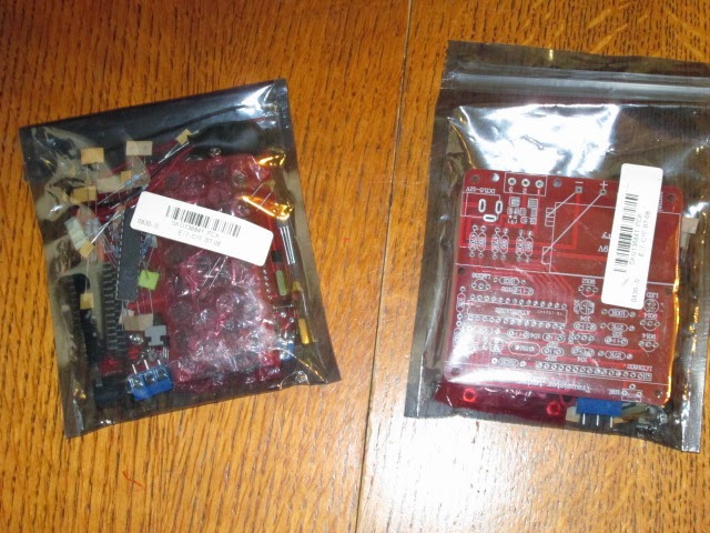
It is basically a copy of the Karl-Heinz Kubbeler design, centred around a programmable ATMEGA328 microcontroller which is very well documented. The kit took about 2 weeks to arrive from China, which contains a well made PCB, display module and all the components, including the blown main chip all for around £8.00 ($12 US). It comes with no instructions on how to put it together, but a Chinese manual is downloadable from the purchase site, which I will make a link available at the bottom of this Blog. Infact, really you don't need the manual for construction, as the component values are printed on the PCB, it just helps a little to get one or two things installed the right way around like the switch, and the circuit diagram can be useful for component reference and maybe fault finding later? Of course the Chinese manual is written in Chinglish, we are refered to welding not soldering! I don't think my old arc welder would prove very suitable for this project somehow? Hi!
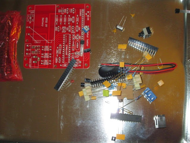
I emptied all the components out of their anti-static packet into an empty biscuit tin, so I didn't lose any of them. I was away, it took around 2 hours of soldering, and sorting out the correct values, a DMM can help with the resistors values, as I found an orange band can look like a red, so its best to measure them to avoid confusion and getting one soldered in the wrong position. Transistors are marked to board values, and the marking of the outline makes sure you cannot put the devices in the wrong way around.
At this stage it is time to check the board over for shorts, man made solder links etc, and snip off component ends. All looked ok, time to connect the 9V battery, before inserting the main ATMEGA IC, at this point a DMM is required to check for regulated 5V at the IC socket pins 7 & 22, all confirmed correct and the regulator was doing its job!
All in all it was quite a relaxing project to put together, I didn't find anything too difficult, although a bit of care is needed aligning up the pins of the main chip before pushing firmly home into its socket.
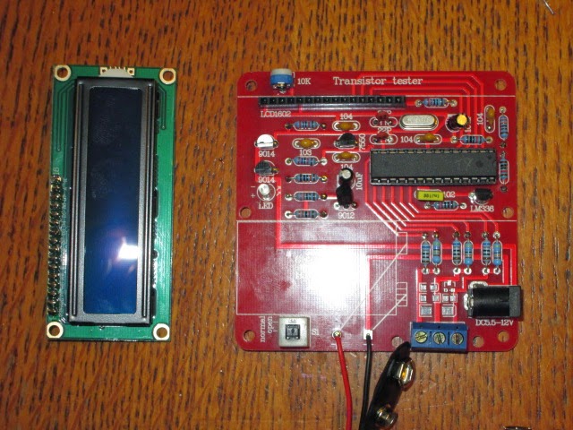
There is not much work to do with the display board as most of this is already constructed, just a strip of header pins that carefully require soldering in across the top of its PCB. This then mates up with the socket strip on the main board when it is pushed home and bolted together.
All looked good time to switch on! If it fires up correctly one push of the On button should turn on the display. In my case it did, and didn't? When I released the Push To Make switch, it went out ? Some folk have had problems putting the switch in the wrong way around, I knew I hadn't done this and a quick check confirmed the switch had been inserted correctly, time to investigate further? The clue was the LED under the display board wasn't on, a quick check with the DMM around the circuit in this area confirmed my thoughts, I had put the LED in the wrong way, huh! Oh dear! I had to pull it all apart, split the two boards desolder and turn the LED around, and then put it all back together.
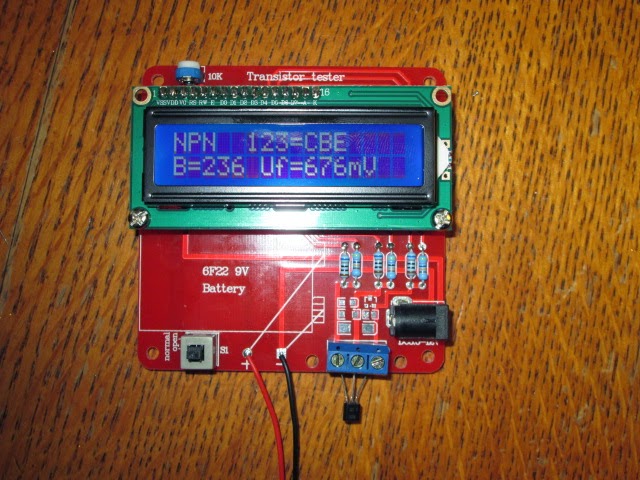
Great it then fired up correctly, and held in its On state after pushing and releasing the button, a quick adjustment of the contrast pot to get the display correct and all was looking well, time to calibrate..
To be continued in part 2.
References:
This is where I purchased the kit from, although they are available from ebay too:
http://www.banggood.com/DIY-Meter-Tester-Kit-For-Capacitance-ESR-Inductance-Resistor-NPN-PNP-p-929603.html
Construction manual:
https://www.dropbox.com/s/zpjwo3vfv9yfr5b/SKU136841%20M8install.pdf
Design manual helps with Calibration and other stuff:
www.mikrocontroller.net/attachment/143813/TTester_096k.pdf
Newer version of manual:
www.mikrocontroller.net/attachment/164956/ttester_eng104k.pdf
Steve, G1KQH, is a regular contributor to AmateurRadio.com and writes from England. Contact him at [email protected].This could prove to be a very useful piece of component test kit, for the constructor and repair bench, including the novice. It does, R, L, C including ESR, Diodes and Transistors, giving the pin configuration detail of the Semiconductor device undertest as well as the useful gain figures.
It is basically a copy of the Karl-Heinz Kubbeler design, centred around a programmable ATMEGA328 microcontroller which is very well documented. The kit took about 2 weeks to arrive from China, which contains a well made PCB, display module and all the components, including the blown main chip all for around £8.00 ($12 US). It comes with no instructions on how to put it together, but a Chinese manual is downloadable from the purchase site, which I will make a link available at the bottom of this Blog. Infact, really you don't need the manual for construction, as the component values are printed on the PCB, it just helps a little to get one or two things installed the right way around like the switch, and the circuit diagram can be useful for component reference and maybe fault finding later? Of course the Chinese manual is written in Chinglish, we are refered to welding not soldering! I don't think my old arc welder would prove very suitable for this project somehow? Hi!
I emptied all the components out of their anti-static packet into an empty biscuit tin, so I didn't lose any of them. I was away, it took around 2 hours of soldering, and sorting out the correct values, a DMM can help with the resistors values, as I found an orange band can look like a red, so its best to measure them to avoid confusion and getting one soldered in the wrong position. Transistors are marked to board values, and the marking of the outline makes sure you cannot put the devices in the wrong way around.
At this stage it is time to check the board over for shorts, man made solder links etc, and snip off component ends. All looked ok, time to connect the 9V battery, before inserting the main ATMEGA IC, at this point a DMM is required to check for regulated 5V at the IC socket pins 7 & 22, all confirmed correct and the regulator was doing its job!
All in all it was quite a relaxing project to put together, I didn't find anything too difficult, although a bit of care is needed aligning up the pins of the main chip before pushing firmly home into its socket.
There is not much work to do with the display board as most of this is already constructed, just a strip of header pins that carefully require soldering in across the top of its PCB. This then mates up with the socket strip on the main board when it is pushed home and bolted together.
All looked good time to switch on! If it fires up correctly one push of the On button should turn on the display. In my case it did, and didn't? When I released the Push To Make switch, it went out ? Some folk have had problems putting the switch in the wrong way around, I knew I hadn't done this and a quick check confirmed the switch had been inserted correctly, time to investigate further? The clue was the LED under the display board wasn't on, a quick check with the DMM around the circuit in this area confirmed my thoughts, I had put the LED in the wrong way, huh! Oh dear! I had to pull it all apart, split the two boards desolder and turn the LED around, and then put it all back together.
Great it then fired up correctly, and held in its On state after pushing and releasing the button, a quick adjustment of the contrast pot to get the display correct and all was looking well, time to calibrate..
To be continued in part 2.
References:
This is where I purchased the kit from, although they are available from ebay too:
http://www.banggood.com/DIY-Meter-Tester-Kit-For-Capacitance-ESR-Inductance-Resistor-NPN-PNP-p-929603.html
Construction manual:
https://www.dropbox.com/s/zpjwo3vfv9yfr5b/SKU136841%20M8install.pdf
Design manual helps with Calibration and other stuff:
www.mikrocontroller.net/attachment/143813/TTester_096k.pdf
Newer version of manual:
www.mikrocontroller.net/attachment/164956/ttester_eng104k.pdf
5 Responses to “Building the M328 component tester (1)”
Please support our generous sponsors who make AmateurRadio.com possible:
 Ham Radio Deluxe |
 Ham Radio Prep |
 KB3IFH QSL Cards  Hip Ham Shirts  HamRadioAuctions HamRadioAuctions Reliance Antennas Reliance Antennas Enigma Shop Enigma Shop |  morseDX  Ni4L Antennas  R&L Electronics R&L Electronics antennas.us antennas.us Ears to Our World Ears to Our World |
- Matt W1MST, Managing Editor

Wow.
Thanks for the hints! Worked First time. Now looking for the calibrate post.
Good to hear you got it going Jim, and found the info valuable. Chinese kits can be a challenge at the best of times. Good luck with the calibration, follow the steps and you will find that will work 1st time too.
73 Steve
Hi
I’m a novice electronics hobbiest. Kindly write an article and guide us how to upgrade the M328 16×2 tester firmware using the Arduino ISP.
Your guide are greatly appreciated. Thanks.
Hello Steve,
I have built a slightly different version to yours mine has three SMDs components, a chip cap, a six pin i/c with no markings to indicate pin 1 !!!! and another device which I can only assume to be a zenner, I assume the zenner is for for some sort of protection as it is shown on the board as dual polarity but no markings on the device !. Powered up the board without the i/c and it is drawing would you beleive some 223 m/a at 9 volts!!! been over the board umteem times, but can find no mistakes that I have made, however, will pursue and let you know.
Vri 73 de George G4EUF.